Complicated Roof Framing Made Easy
Description
This section is from the book "Hicks' Builders' Guide", by I. P. Hicks. Also available from Amazon: Hicks' Builders' Guide.
Complicated Roof Framing Made Easy
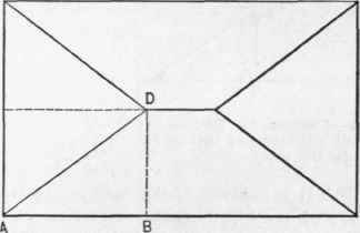
Fig. 65. - Plan of an Irregular Hip Roof.
Let us now take the plan of a hip roof building having a long run of common rafter on one side of the hip and a short run on the opposite side. This kind of a hip is called an irregular hip, because the base line or run of the hip is not on an angle of 45° with the plates, as in the regular hip. In Fig. 65 A B is the run of common rafter on the left side of the hip and the long run. B D is the run of common rafter on the right side of the hip and the short run, A D being the run of the hip rafter. Now, to make everything plain and avoid the confusion of cross lines which are so troublesome to the inexperienced it is better to make separate diagrams showing each succeeding step as the plan progresses until all is made clear; then one can adopt the plan of separate diagrams or he can combine the whole in one if desired. To beginners separate diagrams are recommended, especially in connection with complicated roofs.
Referring now to Fig. 66, A B is the run of common rafter on the left side of the hip, B E the rise of roof and A E the length of common rafter for the long run. A bevel set in the angle at E will be the plumb cut or down bevel at the top, and a bevel set at A will give the bottom cut fitting the plate. Next set off the run of common rafter on the right side of the hip, B C, and connect E with C for the length of the common rafter for the short run. A bevel set in the angle at E will give the down bevel at the top and at C the bottom cut. We will now proceed to find the hip rafter and bevels for cutting the same. A B is the run of the common rafter on the left side of the hip, B D the run of common rafter on right side of hip, while A D is the run and angle the hip makes with the plates. From D square up the rise of the roof to F; connect F with A, and we have the length of hip rafter. A bevel set in the angle at F will give the down bevel at the top and at A the bottom bevel fitting the plate.
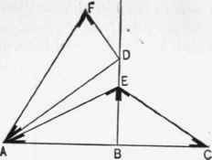
Fig. 66. - Diagram for Finding the Lengths and Bevels c f Rafters for Irregular Hip Roofs.
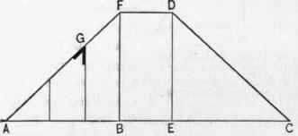
Fig. 67. - Lengths and Bevels of Jack Rafters.
The next step will be to show the length and bevels of the jack rafters. Referring now to Fig. 67, draw a horizontal line, as A C, representing the length of plate in the plan. From A set off the run of the common rafter on the left or long run to B. From B erect a perpendicular to F, which is the length of common rafter on the short run and shown by E C in Fig. 66. Connect F with A, and the hip line is in position for finding the lengths and bevels of the jacks on the side of the building having the short run of common rafter. Space the jacks on the line A B and draw perpendicular lines joining the hip line. This will give the lengths of jacks, and a bevel set in the angle at G will give the bevel across the back of the same The plumb cut or down bevel will be the same as that of the common rafter on the short run. F D shows the length of ridge and the space which the common rafters occupy. C E D shows a space for jacks similar to A B F. It is unnecessary to draw the jacks in this space, and it is therefore left blank. The next step will be to find the lengths and bevels of the jacks on the end of the building having the long run of the common rafter. Referring to Fig. 68, let A C represent the width of the building, A B the run of the common rafter on short run, B F the length of common rafter on long run and the same as shown by A E in Fig. 66. Space the line A B for the jacks and draw perpendicular lines joining the hips. A bevel set in the angle at L will give the bevel across the back. The plumb cut or down bevel will be the same as that of the common rafter on the long run. Now everything desired has been shown, and without the confusion of cross-lines. By this method all complications in roof framing are made easy. And the most difficult roofs will show the superiority of this plan, as it is rarely ever necessary to cross a line, and if necessary every rafter maybe shown. For roofs having hips and gables of varying pitches this plan has no equal. In Fig. 69 is shown how Figs. 66, 67 and 68 may be combined to indicate the different lengths and cuts of all the rafters directly from the plan.
This method is attended with many cross lines and is not recommended even to the most experienced, for, in connection with complicated roofs, there is danger of making mistakes. Referring to the plan, Fig. 69, A B is the run of the common rafter on the left side of the hip, and the long run B E is the rise, A E being the length. A bevel set at E on the line A E will give the plumb cut or down bevel, and at A the bottom bevel. B C is the run of the common rafter on the right side of the hip, and the short run B E the rise and E C the length. A bevel set at E, on the line C E, will give the plumb cut or down bevel, and at C the bottom bevel.
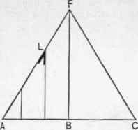
Fig. 68. - Finding Lengths and Bevels of Jack Rafters on the End of Building Having the long run of the Common Rafter.
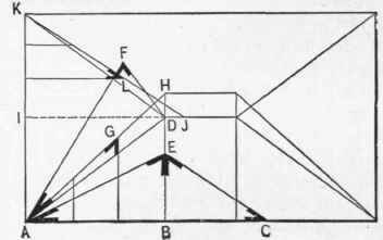
Fig. 69. - Showing how several Diagrams may be combined to indicate directly from the Plan the different Length and Cuts of all the Rafters.
A B is the long run of the common rafter, B D the short run of the common rafter, A D the angle and run of the hip, D F the rise of the hip and A F the length of hip rafter. The bevel at F is the down bevel and at A the bottom bevel. B H is the length of the common rafter for the short run and the same as C E, while A H is the hip dropped down in position for finding lengths and bevel for jacks on the side of the roof having the short run of the common rafter. The jacks are spaced on the line A B and drawn perpendicular, joining the hip line A H. A bevel set in the angle at G will give the bevel across the back.
The plumb cut or down bevel is the same as that of the common rafter on the short run, and is shown at E on the line E. C. The letters I J represent the length of the common rafter for the long run, which is the same as A E ; then J K is the length and position of the hip for finding lengths and bevel for the back of the jacks on the side having the long run of the common rafter. Space the jacks on the line I K and draw them at right angles joining the hip line K J. A bevel set in the angle at L will give the bevel across the back of the same, the down bevel being the same as that of the common rafter on the long run. It is shown at E on line E A. In Fig. 69 all the work is shown in one diagram very plainly, yet to many it may appear somewhat complicated. Two pitches in one roof always make a complication of bevels, often requiring many lines to illustrate. As a proof of the correctness of this method observe the following point : A F, A H and J K each represent the hip rafter, showing it in different positions, and if the work is right these lines must be of the same length. A F is the position of the hip for finding the cuts, while A H is the position of the hip for finding the bevel for the back of the jack on the short run. J K is the position for finding the bevel for back of jack on the long run. Having shown the most practical system of hip roof framing, let us now consider it ; application to some of the most complicated plans which frequently come up in actual practice.
Continue to:
My Books

