Mitering Planceers, Moldings, Etc
Description
This section is from the book "Hicks' Builders' Guide", by I. P. Hicks. Also available from Amazon: Hicks' Builders' Guide.
Mitering Planceers, Moldings, Etc
As the art of making a common miter joint is universally understood by all mechanics, an explanation of the common miter is unnecessary. We will, therefore, explain the methods of making some of the most complicated and difficult miters which frequently come up in the actual practice of carpentry. Fig. 107 shows the elevation of a roof having three gables, and it is required to miter the level planceer A B with the gable planceer B C. To many this seems like a difficult problem; yet if one will con sider the roof plan for a moment, he will see that the proper figures on the square to make the required miter may be taken directly from the roof plan, which gives the bevels for cutting the rafters.
To cut the bevel on the planceer A B use the same figures on the square that make the bevel across the top of jacks, but reverse the cut. Thus, if 17 on blade and 12 on tongue cuts the jack rafters, the blade gives the cut of the jack and the tongue the miter line for the planceer. The reason for reversing the cut is because the planceer A B runs in a direction exactly opposite the rafters.
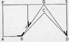
Fig. 107. - Elevation of Roof Having Three Gables.
The same figures will also miter the sheeting in the valley. Now, the planceer B C which goes up the gable runs parallel with the rafters, hence the same figures which give the cut for the jacks will give the cut for this, which, in the present case, are 17 on the blade and 12 on the tongue, the blade giving the cut. Or, referring to Fig. 107, B G and D G show the position and length of valley rafters, and the bevel at B is the bevel for cutting the planceer A B, while that at J, which is the bevel for jack rafter, is the bevel for cutting the planceer B C, which goes up the gable. The junction of the two gable planceers C D and E D at D forms another kind of miter joint. In this the planceer on both gables cuts the same, and the cut is the same as the bevel which cuts the jacks, shown at D. This bevel is also the same as the one shown at J.
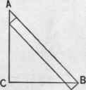
Fig. 108. - Diagram for Finding Width of Gable Planceer.
The planceers A B and B C must necessarily be of different widths, the gable planceer being the narrower. To find the width the gable planceer must be to match the level planceer, draw the width of level planceer A B, representing the pitch of roof, as shown in Fig. 108. Square down from A to C, the rise of planceer, and B C will be the width of gable planceer corresponding to A B. To obtain the miter line for mitering the fascia and crown molding at B, draw two parallel level lines and two parallel pitch lines of the common rafter, keeping both sets of lines the same distance apart, as shown in Fig. 109. Connect the opposite angles where the lines cross each other, as shown by A B, and this will give the required miter. The figures for this may be found by placing the blade of the square on the line A C and tongue on A B. The tongue gives the cut If the fascia stands square with the rafters on the line A B, Fig. 107, then a square miter will make the joint which connects the level fascia A B with the gable fascia A F. But now suppose the fascia on line A B stands plumb, as it frequently does, and should on a roof of this kind, then a different cut is required. In this case cut the level fascia on a square miter, but for the gable fascia cut across the edge of the board on the same bevel as for a jack, and cut the plumb line the same as that of the common rafter. Having shown how to properly miter the planceer and fascia, we will next take the crown molding. The miter for moldings cannot be accurately laid off from the square because it cannot be properly applied to them; hence the best way to miter moldings is by means of the miter box. As almost every one knows how to make the common miter box I will not go into the details of manufacturing it, but explain the methods of making cuts in it for the purpose of mitering moldings for some of the difficult joints which frequently come up in actual practice.
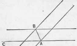
Fig. 109. - Method of Obtaining Miter Line for Fascia and Crown Molding.
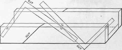
Fig 110. - Manner of Applying the Square to the Miter Box for Laying Off the Cuts.
To miter the molding in the valley at D, Fig. 107, which is the junction of two gables, take for the cut down the sides of the box the plumb cut of the common rafter, which in this case I will suppose to be one-half pitch, which is in accordance with the diagrams. For the cut across the top of box use the same bevel as for cutting the jacks, which is shown at J. Fig. no shows the manner of applying the square to the box for laying off the cuts. It will be necessary to put two cuts in the box, right and left, as shown. In connection with this kind of a box it is more convenient to make it with only one side, as shown in Fig. III. The side, however, should be made of a thick piece of lumber, so that it will form a good guide for the saw. As these miter boxes are used only for a special purpose no one wants to spend very much time making them, therefore the box with one side is recommended to answer the purpose, and it is the easiest to make. The secret of a good miter box lies in having the sides stand square with the bottom and of the same hight from end to end If these two points are carefully observed and the cuts made true, good results will follow, no matter how rough the box may be in appearance.
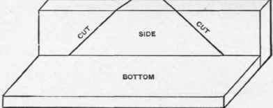
Fig. 111. - Miter Box with One Side.
To miter the level molding at A, in Fig. 107, with the gable molding A F, cut the level molding A B in a common miter box, using the square mitt r, and cut the gable molding A F in the box as described in connection with Fig. no. By this method a fair job can be done, but the moldings will not member exactly. To make a perfect joint the gable molding requires a slightly different profile.
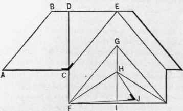
Fig. 113.-Hip and Valley Roof of One-Third Pitch.
Fig. 112 shows the elevation plan of a hip and valley roof drawn to the scale of a third pitch, in which is shown another form of miter joints. A B is the length and position of left end hip rafter, C D the length of common rafter, C E the length and position of left valley rafter, F G the length and position of left hip on front end, and F H the length of common rafter. A B, C E and F G show the miter lines of hips and valleys. There is nothing peculiar or difficult about the joints at A, C and E except the mitering of the fascia and crown molding on a square cornice, which means that the ends of the rafters are cut square and that the fascia and crown molding stand square with the roof instead of plumb. To miter the sheeting or the planceer on the hips or in the valley, take the length of common rafter C D on the blade and the run of common rafter D E on the tongue. The figures for a third pitch are 14½ inches on blade and 12 inches on tongue, the tongue giving the cut, or the bevel may be taken at C, as shown in the diagram. There is also a bevel across the edge of the board, which may be found in the following manner : Take the length of common rafter F H on the blade and the rise of common rafter I H on the tongue. The figures for a third pitch are 14½ inches on blade and 8 inches on tongue, the tongue giving the cut, or the bevel may be found as follows : Square down on the line F H the rise of common rafter H J and connect J F. The bevel at J will be the bevel for the edge of the board.
There is practically no difference between a hip and valley cut. The bevel on the edge of board in the valley and on the hip is the same, it being only neces sary to reverse the bevel, as the long point of bevel on hip will be on the face side of board and in the valley it will be on the back side.
To miter the fascia at A, C or F when it stands square with the roof proceed as follows : For the bevel across the edge of board take the length of the common rafter on the blade and the run on the tongue, when the tongue will give the cut. Figures on the square are the same as for cutting the face side of sheeting or planceer, or the bevel may be taken, as shown at C. For the cut down the side of fascia take the length of the common rafter on the blade and the rise of common rafter on tongue, and the tongue will give the cut, or take the bevel shown at J.
To make the cut on a miter box for mitering the molding on the hips and valleys take the bevel at C for the cut across the top of box, which is 14½ inches on blade and 12 inches on tongue. The tongue gives the cut. For the cut down the side of box take the bevel at J, which is 14½ inches on the blade and 8 inches on the tongue The tongue gives the cut. The facts when condensed are as follows:
Length of common rafter, 14½ inches on blade, and run of common rafter, 12 inches on tongue, gives cut for face of planceer or sheeting. The tongue gives the cut.
Length of common rafter, 14½ inches on blade, and rise of common rafter, 8 inches on tongue, gives cut for edge of planceer or sheeting. The tongue gives the cut.
Length of common rafter, 14½ inches on blade, and run of common rafter, 12 inches on tongue, gives cut for edge of fascia. The tongue gives the cut.
Length of common rafter, 14½ inches on blade, and rise of common rafter, 8 inches on tongue, gives cut for side of fascia. The tongue gives the cut.
Continue to:
My Books

