Joints In Tension. - Lap Joints
Description
This section is from the book "Notes On Building Construction", by Henry Fidler. Also available from Amazon: Notes on building construction.
Joints In Tension. - Lap Joints
Fig. 222 shows the arrangement of rivets generally adopted for lap joints which are to undergo a tensile stress.
The object of so placing the rivets is to keep the strength of the joint as nearly equal to that of the original plate as possible.
In this case the strength of the joint may be arranged so as to be equal to that of the cross section of the plate, less one rivet hole.1
It is true that the weakest section of the plates themselves is at A B, where they are pierced by three rivet holes; but before either plate could break at this line, the three rivets, opq or rst, within the line must be shorn in two.
Thus, before the upper plate can tear at A B, of q must be shorn; and before the lower plate can give way at AB, the rivets rst must be shorn.2
This can be shown by figures as follows: -
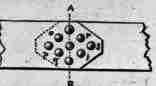
Fig. 222. Calculation.
Suppose the plates to be 8" wide and 3/8" thick - joined by 3/4" rivets - and that the tensile strength of the iron is 20 tons per square inch, and its resistance to shearing 16 tons per square inch, then
A. If the joint could fail by one of the plates tearing across A B and shearing three rivets (either opq or rst), the under-mentioned resistance must be overcome.
Rivets.
Plate less 3 rivet holes = (8"- 3 x 3/4) x 3/8" x 20 tons
= 43.1 tons.
Shearing area of rivet.
Shearing resistance 3 rivets = π x (3/4)2
4 x 3x 16 tons -
= 21 tons.
The total resistance will be = (43.l + 21)
= 64.1 tons.
B. If the joint could fail by tearing a plate through rt or oq and shearing one rivet at s or p, the resistance would be
Plate Less 2 Rivet Holes = (8"
2 x 3/4) x 3/8" x 20 tons = 487 tons.
Shearing resistance 1 rivet= π x (3/4)2 1 x 16 tons = 7 tons. Total resistance = 55.7 tons.
C. If the joint were to fail by the plate tearing across through s or p, the resistance to be overcome would be
Plate less 1 rivet hole = (8" -3/4) x 3/8" x 20 tons
= 54.4 tons. Therefore, as the resistance through s or p is (as is shown at C above) less than the resistance at either of the other sections as shown at A or B, the joint will fail by tearing across through s or p - that is, it is equal to the strength of the plate less one rivet hole.
1 To ensure this, the loss of tensile strength in a plate caused by a rivet hole must not be greater than the shearing strength of a rivet.
2 Shearing
A rivet is shorn when by the sliding movement of one or both of the plates through which it passes it is cut through horizontally.
Again it has been suggested that the joint might fail
D. At the centre by the fracture of the two plates pierced by three rivet holes. This, however, is not the case.
The effective strength or resistance of the two plates would be
2 plates less 3 rivet holes = 2 (8" - 3 x 3/4) 3/8"x 20 tons = 86.2 tons.
This assumed section of rupture offers therefore more resistance than any of the others, and the joint cannot fail here.
Working Stress
In practice the stress allowed upon the joint would be only 1/4 of the breaking stress taken above, and the working stress allowed would therefore be 1/4 of the weakest resistance = 54.4/4 =13.6 tons.
Butt Joints
The same principle may be applied to a joint with cover plates, as shown in Fig. 223. The arrangement is similar to that in Fig. 222, but with two rivets at the weakest part.
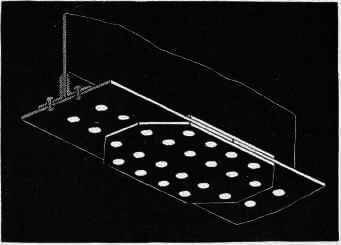
Fig. 223.
The riveted joints of tension booms of girders are very commonly arranged in plan, as shown in Fig. 223.
Joints In Compression
It was at one time thought that for a butt joint under compression very few rivets were necessary; that the whole strain was communicated by the end of one plate to the other upon which it pressed; and that the rivets would be required only to keep the plates in their places.
Experience has shown, however, that in practice we cannot depend upon the plates being so closely butted against one another as to transmit the thrust direct (see p. 89).
"Very slight inaccuracy of workmanship may cause the separation of the butting plates, and then the whole thrust is transmitted through the rivets and through the cover plates."
"For the best bridges it is now assumed that all the joints shall be of sufficient strength to take the whole strain, if necessary, through the rivets."
" The only way in which compression joints may safely differ from tension joints is, that the rivets may be more closely spaced across the plate, .the quantity punched out in any section not affecting the strength of a compression joint as it does that of a tension joint."1
Grouped Joints
The joints that occur in the plates of riveted girders are generally formed with cover plates.
When there are several layers of plates, as in the booms of a large girder, the joints may with advantage be collected into groups, so that several may be covered by one pair of plates, as shown in Fig. 224.
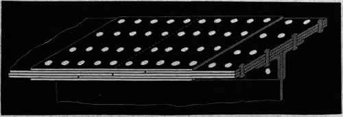
Fig. 224. Grouped Joint.
Fig. 224 shows the joints in the three plates of the boom of a heavy girder collected under cover plates. The joints may be chain or zigzag riveted in plan; or in some cases the cover plates are cut off obliquely, so as to have triangular ends, and the rivets are arranged somewhat as in Figs. 222, 223.
Essentials Of Good Riveting. - Rivet Holes
The holes in plates to be riveted may be either punched or drilled.
In whichever way they are formed, it is important that they should be cut clean and true, and should fit exactly over one another. If they do not, an irregular cavity is formed, which has to be forcibly straightened by a steel pin or "drift punch " before the rivet is inserted, thus injuring the plate, enlarging the hole, and causing the rivet to fit loosely.
Some difference of opinion has existed as to whether punched or drilled holes make the best work.
Punched Holes
The punched hole is slightly conical in shape; thus the rivet filling the hole in two plates is of a double conical shape. It is, of course, important that the hole should be punched so that the narrow part of the cone is on that side of each plate which meets the other plate. Such rivets "have been known to hold the plates together even after the heads have been removed by corrosion."
1 Unwin, Iron Bridges and Roofs.
This is a great advantage in shipbuilding and boilermaking, but in girder work rivets are seldom subject to a strain in direction of their length.
In practice the conical shape is often destroyed and its advantages lost by the insertion of the drift above referred to.
The process of punching is, however, not so accurate as drilling; it tears and injures the plate round the edges of the holes, especially when the iron is not of good quality.
Drilled Holes
On the other hand, drilled holes may be accurately formed without the slightest injury to the plate, and of a diameter smaller than the thickness of the plate. When there are many plates to be united, so that multiple drills can be used, the cost is not greater than that of punched holes; and the advantage gained in the work coming together properly, and the rivet holes being fair, is very great.
The sharp edges of drilled holes have been found by experiment to expedite the shearing of the rivets. To prevent this the edges of the holes have in some cases been rounded, which has been found to increase the resistance of the rivet by about 10 per cent.1
Cases in which Drilled Holes and Punched, Holes may respectively he used. - To sum up, we may say that in really first-class work, when several layers of plates have to be riveted together, when small scantlings are used as in some roofs, or when the rivet holes are of a diameter less than the thickness of the plates, it is desirable that the holes should be drilled.
When the quality of the iron is inferior, drilled holes become a necessity.
Holes for ordinary work, those in thin plates, and those of a diameter greater than the thickness of the plates, may be punched.
Sometimes the holes are punched smaller than required, and the rough injured edge afterwards drilled or "rimered" out.
Heating
Eivets should be heated uniformly throughout their whole substance; not raised above a dull red (by daylight); not twice heated.
The heating should be effected in an air furnace, the rivets being kept clear of the fuel.
1 Sir William Fairbaim. Proceedings of Royal Society, 24th April 1873.
An ordinary fire heats the rivets partially, and so quickly that they are frequently burnt.
The usual plan is to arrange the rivets in a flat plate full of holes, through which their tails protrude. This plate is placed upon the fire, and thus the tails become very hot - sometimes white hot - while the heads remain comparatively cool.
For riveting by hand, however, it is desirable that the head of the rivet should be even hotter than the point, otherwise the blows which are sufficient to expand the rivet and make it fill the hole near the point will not have so much effect at the other end, and the rivet will not quite fill the hole near the head.
It is of the utmost importance that rivets should not be overheated, otherwise the iron will lose its ductility, and the rivets will become weak and brittle.
If proper attention be not paid to this point, much injury may be done by too large a number of rivets being put into the fire at once to save trouble, and consequently left there too long.
Arrangement
All rivets should be arranged in such positions that both ends can be got at during construction.
Causes Of Failure
Eiveted joints are liable to fail in different ways, according to their form and the nature of the stress brought upon them.
Among the causes of failure are the following: -
The rivets themselves may fail by their heads being shorn off, by the pins being ruptured under a tensile stress (though rivets should, as a rule, be subjected only to shearing stress), or by the pins being cut in two by a shearing stress.
Any plate may fail either by the inability of its "effective section" (that is, the section of the plate left after the rivet holes are cut out) to resist the stress, or by the rivets shearing through the portion of plate beyond them. In some cases also, where the rivet has not sufficient bearing area, it indents and crushes the plate round the edge of the hole, or again the plate may indent and injure the rivet, and causes a loose joint.
For important work it is necessary carefully to calculate the stresses which will come upon a joint, and to arrange the number, size, and position of the rivets, their distances apart, and the dimensions of the plates accordingly. Such calculations are, however, beyond the province of this part of the course, and will be entered upon in Part IV.
Continue to:
My Books

