King-Post Roof
Description
This section is from the book "Notes On Building Construction", by Henry Fidler. Also available from Amazon: Notes on building construction.
King-Post Roof
When it is attempted, however, to apply the last-mentioned construction to large spans, it is found that the weight of the roof covering, of snow, and the pressure of the wind upon the rafters, are too much for them, and that they have a tendency to bend.
It is necessary, therefore, that they should be supported in the middle, and this is done by means of wooden props called "braces " or "struts" (S S, Fig. 321), which afford a more direct support to the rafters than a collar beam would do.
These struts are placed with their upper ends under each rafter, near its centre point,2 their lower ends being secured to the vertical tie of the roof.
It is somewhat inconvenient to attach the feet of the struts to an iron rod and therefore the vertical tie in wooden roofs is generally made of timber and called a "King Post" or "King Piece," the head and feet of which are conveniently shaped to receive the rafters and struts.
The struts mag, however, be fixed to the foot of an iron king bolt, as shown in Figs. 204 and 330.
The rafters, being now supported in the centre, are reduced to half their former bearing, and are able therefore to bear twice the load that they could before have sustained.
The resulting framework (see Fig. 321), consisting of the rafters (PR), king post (KP), struts (S), and tie beam (T), is known as a King-post Truss.

King-rod Roof [without Struts).
1 In order to obtain a really stiff ceiling, it is a good plan to introduce heavy tie beams or binders, at intervals of 8 or 10 feet in the length of the roof, supported in the centre by an iron rod, as shown. These beams act as ties, and also carry the ceiling joists, which then run at right angles to them, and are notched to their under side.
2 With regard to the exact position of the struts, see p. 164.
Such a truss is well adapted for roofs having a span not exceeding 30 feet.
The remaining parts shown in Fig 321, lettered CR, P, B, G,pp, and r, are not portions of the truss itself, but are supported by it.
It would for many reasons be inconvenient to have trusses such as that just described so close together that they would carry the boarding slates or other roof covering without any intermediate bearers.
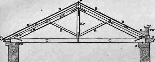
Fig. 321. King-post Truss.
Occasionally very light trusses, made simply of narrow pieces of boards nailed together in something like the king-post form, are so used, but the general practice is to set up trusses along the building,1 about 10 feet apart, and each strong enough to bear the weight of the portion of roof (one "bay") that will be carried by it.
Across these trusses or "Principals " are laid purlins (PP), and upon the purlins are fixed smaller or " common rafters " (CR), which carry the boarding, B (or battens where they are used), for the slates.
Other members are also found necessary, such as wall plates (wp) to grip the ends of the tie beam and to distribute the weight over the walls; a ridge piece (r) to unite the tops of the trusses longitudinally and receive the upper ends of the common rafters; and pole plates (pp) to receive the feet of the common rafters.
Fig. 322 represents part of a king-post roof showing two principal trusses with some of the members resting upon them, nearly all the boarding being omitted, and also most of the common rafters between the principals, in order that the trusses and purlins may be seen more distinctly.
The walls supporting the roof are surmounted by parapets; part
These should be over the piers between the windows, not over the openings.
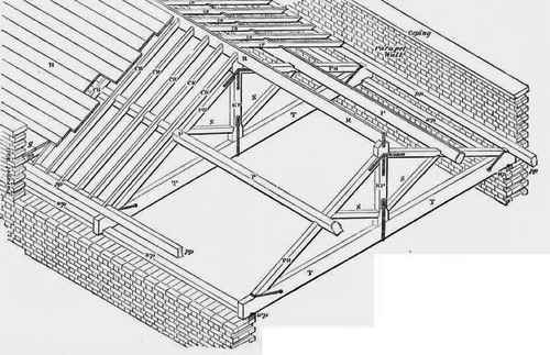
Fig. 322. Part of a KING-POST ROOF, showing two Trusses, etc.
See page 159, of one is broken away in order to show the roof timbers and a portion of the woodwork of the gutter formed behind it.
Continue to:
My Books

