Different Soils
Description
This section is from the "Practical Building Construction" book, by John Parnell Allen. Also see Amazon: Practical Building Construction.
Different Soils
In dealing with the following different kinds of ground, it must be understood that the remarks are made in a general sense, and are not intended to lay down any hard-and-fast rule, as in all cases personal inspection of the site is absolutely necessary before deciding on any points with regard to foundation work.
Solid rock in foundations cannot be bettered when it is sound and alike all over, so that it would be ridiculous to take it out merely to replace it by an inferior article such as concrete. However, the bottom should be made truly level; or, if it is uneven by nature, the loose inferior portions should be taken out, and those places arched over to and from the solid, or concrete should be put in, lapping at the joints.
Gravel is the next best and most suitable soil for a sound foundation; and where it is sound it cannot be improved upon, though when it is loose and coarse it should be grouted with lias lime or cement-mortar of required strength, according to circumstances, or otherwise a thin bed of concrete may be put in the trench on the top of the gravel.
Foundations of loose gravel, however, are apt to slip, and consequently the sides must be shored by one or other of the following methods: In tolerably good ground poling boards, in size about 9x2 inches or 9 x 3 inches, are placed at intervals, in pairs, on each side of the trench, and strutted apart by stout members, small pieces of scaffold poles, from 4 to 6 inches in diameter (as Fig. 904), being generally sufficient for the purpose. But where the ground is looser the poling boards must be placed close together, perpendicularly, with walings, which are placed horizontally inside them, and strutted from one to the other, at intervals of every 2 to 4 feet, as Fig. 905; the poling boards, in this case, varying from 1 1/2 to 3 inches thick, and the walings being usually 11X3 inches.
Fig. 904.
Fig. 905.
In running sand it will be obvious that it is impossible to wait until a sufficient depth has been dug out to allow of vertical poling boards being used without the sides previously slipping in; wherefore sheeting, as shown in Fig. 906, is used, laid longitudinally, and secured by poling boards and strutted, as in the first instance (Fig. 904).
Reverting to the consideration of the various natural grounds, the next in order as a substantial formation is a good hard, sound clay, which should lie in horizontal strata, as a dipping clay is apt to slip downwards and cause settlements. It is necessary that clay should be well drained, so that the rain shall not have time to affect it so much as to cause any considerable alteration; and the bottom of the concrete, or top of the clay, should be at such a depth as to be beyond the influence of heat, as it is well known that the sun is very apt to cause deep and frequent cracks in clayey ground.
Fig. 906.
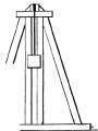
Front Elevation Fig. 907.
Excavations in hard clays do not always require shoring, though it is advisable to adopt that precaution in the case of the weaker kinds of clay.
Chalk, from its nature, is a very uncertain foundation; though the harder and better qualities may sometimes be as good as rock, while the softer kinds are always very bad, and liable to be greatly affected by wet crete. Where such sand and other boggy and soft soils are present and of considerable depth, so that the bottom thereof cannot be reached without too much trouble and expense, for their removal, as ought to be done, platforms of wood or fascines are adopted and made to cany the whole building, floating, as it were, on the top of the sand; while, in the better qualities of this loose ground, piles of square timber of considerable length are driven down to a solid foundation.
Sand, in whatever form, and especially quicksand, is a most treacherous soil for foundations, having no power to keep itself together, as it were, so that it must not be taken into any account. The best course is to remove it by excavation, if practicable, and replace it with a layer of con-
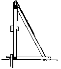
Side Elevation Fig. 908.
Fig. 909.
This is effected by means of heavy weights, called monkeys or rams, being directed on to their top by guides held up by framing, as shown in Figs. 907, 908, and 909, the weights being elevated by hand or by suitable machinery to a certain adequate height, and then allowed to fall on the head of the pile, which is encircled by a wrought iron ring to prevent it from splitting under the force of the impact; while the bottom or point of the pile is shod with an iron-pointed shoe, as Fig. 910.
These piles are from 9 to 12 inches square, and spaced at from 1 to 3 or 4 feet apart in each direction, as shown in Fig. 911, being driven firmly into the solid ground, while their heads are connected by bearers of timber of various sizes into which they are tenoned, and on these bearers are laid the wooden planks.01 stone slabbing on which the foundations are built, as in Fig. 912; the spaces for a short depth, below and between the piles, being occasionally dug out and rilled with concrete to make one solid mass at the top.

Fig. 911.

Fig. 912.
Fig. 919.

Fig. 914.
The use of inverted arches for the distribution of the weight in variable foundations has been dealt with in Chapter III (Brick Reveals, Arches, And Pointing. Reveals),, to which the student is referred.
Sewers
Sewers are large drains, which are of a size beyond the limit of the use of glazed or other piping for the purpose, built of brick, and circular, oval, or egg-shaped in section. It should be pointed out that glazed stoneware pipes are now made in sizes up to 3 feet in diameter, so that brick sewers, on account of their awkwardness, would not be built of any sizes below this limit, to supersede piping.
Therefore, the first kind of brick sewer in general use is what is called a culvert drain, the straight sides and circular bottom being built of brickwork, either 4 1/2 or 9 inches thick, and covered over with stone slabs, as Fig. 913; or the sewer is built quite circular with special bricks, as Fig. 914; though this is the more awkward method of the two.
Where sewers, built on the above lines, are of such large dimensions that true circles would take up too much room, and render them nearly flat where a good curve to the invert is required for the quick flow of sewage, they are built egg-shaped, as Fig. 915; from which it will be seen that the sewage, whether its volume be great or small, has the best and most equal chance of the necessary quick flow in this form, whereas in the circular kind this cannot be the case. As a rule, the bottoms, or invert blocks, should not be of more than 9 inches radius (the smaller the better, within reason), and of glazed stoneware. The general proportion for the widths and heights is that the diameter of the top circle is double that of the bottom or invert, and the internal height from bottom to top three times that diameter, the remaining space between the circles at the side waits being lined in with arcs tangential to both circles.
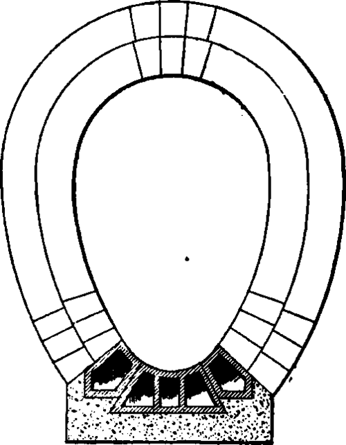
Fig. 915.
Continue to:
My Books

