3. Development Of The Simplest Form Of A Truss
Description
This section is from the book "Building Construction And Superintendence", by F. E. Kidder. Also available from Amazon: Building Construction And Superintendence.
3. Development Of The Simplest Form Of A Truss
The simplest method of supporting a weight between two supports (other than by a beam) is shown in Fig. 1.
Here we have a single load, W, to be supported about half way between the sides of a ravine. If the sides are sufficiently firm it is evident that the load may be supported by means of two inclined posts or "struts" meeting at their upper ends and supported at their lower ends by the ground.
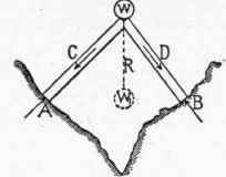
Fig. 1.
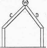
Fig. 2.
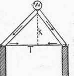
Fig. 3.
It is also evident that the weight W will produce compressive stresses in each of the struts, C and D, which will act in the direction indicated by the arrows.
To keep the struts in position the ground or ledge must offer a resistance in the opposite direction equal to the stresses in the struts, and the surface of the ledge should be exactly at right angles to the axis of the struts.
It may also be taken as evident that the effect on the struts and on their supports is the same whether the load is placed at W or suspended directly from below as at Wl; the only difference between the two cases being that in the latter an additional member, R, is required to transmit the weight to the upper ends of the struts.
The construction shown in Fig. 1, however, is not a true truss, as it exerts an outward thrust on its supports and depends upon them to keep the feet of the struts in position.
It is evident that if the struts C and D were supported only by two vertical posts, as in Fig. 2, the whole structure would immediately fall.
In a building the walls, as a rule, are only intended to support weights which act vertically, and the construction shown in Fig. 1 is not applicable to such conditions. To make it applicable it will be necessary to take up the horizontal components of the stresses in the struts by means of a third member, T, Fig. 3, leaving only the vertical components to be resisted by the walls or other supports.
Continue to:
My Books

