9. Mechanical Principle Of The Howe Truss
Description
This section is from the book "Building Construction And Superintendence", by F. E. Kidder. Also available from Amazon: Building Construction And Superintendence.
9. Mechanical Principle Of The Howe Truss
The action of the pieces in supporting the loads is the same as in truss 20. When the rods and struts are symmetrically disposed each side of the centre, the strut d (Fig. 24) supports 1/2 of W3; strut c,1/2 W3 + W2; strut b, 1/3 W3 + W2 + W1; and the strut a, 1/2 W3 + W2 + W1 + W, although the stress will be increased in the proportion that the length of the struts bears to the vertical distance between centres of the chords. The stresses in the rods also increase in the same proportion toward the ends. On the other hand, the stress in the chords is greatest at the centre, the same as in a beam, the top chord always being in compression and the bottom chord in tension. If the tie-beam or bottom chord is loaded the loads are transmitted by the rods directly to the upper joints, and are added to the loads, W, W1 etc.
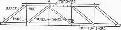
Fig. 21. - Five-Panel Howe Truss.
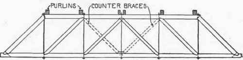
Fig. 22. - Six-Panel Howe Truss.
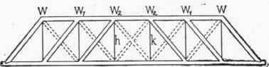
Fig. 23. - Seven-Panel Howe Truss.
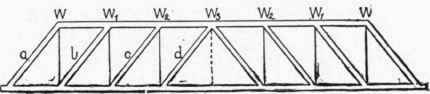
Fig. 24. - Eight-Panel Howe Truss.
When there is no load on the tie-beam, the centre rod of 6, 8 and 10 panel trusses, and the rods each side, of the centre panel (as h and k, Fig. 23,) will have no stress from the roof load, and although they should be inserted to sustain the tie-beam, they need not be more than 3/4 or 7/8-ins. in diameter.
Continue to:
My Books

