Simple Steel Roofs
Description
This section is from the book "Building Construction And Superintendence", by F. E. Kidder. Also available from Amazon: Building Construction And Superintendence.
Simple Steel Roofs
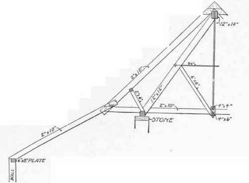
57. Simple steel roofs supported by brick or stone walls are built in very much the same way as wooden roofs with the exception that steel shapes are used in place of the timbers or joists. The connections between the pieces are usually made of bolts and rivets, rivets being used in all the points which can be assembled at the mill, while those joints that have to be made at the building are bolted. Where the span does not exceed 60 feet, angles are almost exclusively used for the members except in cases where the rafters or tie-beams are subject to a transverse strain, in which case a pair of channels or a pair of angles and a web plate are generally cm-ployed. The framing of the roof above the truss will depend in a great measure upon the kind of roofing that is to be used. If the roof is to be of corrugated iron it will be most economical to use 5, 6 or 7-inch I-beam purlins, spaced from 4 to 5 inches apart and bolted to the rafters of the truss, as in Fig. 75, the corrugated iron being secured to the I-beams by galvanized iron straps. The trusses may be spaced from 16 to 20 feet centre to centre. If the roof construction is to be of wood supported by steel trusses the best construction would be to use 10"x12" purlins spaced about 7 feet centre to centre and on top of these spike 2 1/2 or 3-inch planks to support the roofing: this makes a slow burning construction and for an open roof is comparatively cool, and any form of roof covering can be placed on top of it. If a cheaper form of construction is desired the purlins may be spaced from 8 to 10 feet, centre to centre,and 2"x6" jack rafters set on top of them to receive ordinary 7/8 sheathing. The only difference in the cost between this construction and that of the plank roof would be in the 2x6 rafters and 7/8 sheathing, which would cost a little less than the 2 1/2 or 3-inch planks, but it would not offer nearly as good protection from fire or make as cool a roof. The purlins should be secured to the trusses by means of angles bolted to the trusses and lag screwed or bolted to the purlins. The joints in the trusses should always be arranged to suit the spacing of the purlins.

Fig. 128. - Half Transverse Section Through Roof.
58. If an incombustible roof with slate or tile covering is desired the most economical construction would be that shown by Fig. 129, which is a detail of the roof construction of a power-house in St. Louis, designed by Mr. E. W. Stern, C. E., and described in the "Engineering Record" of Feb. 19, 1898.

Fig. 129. - Detail of Slate Covering on Steel Roof.
The roof is supported on riveted trusses carrying horizontal I-beam purlins, which support channel bar jack rafters 5 feet apart. On these elements light uneven legged Z-bars are clamped about one foot apart, parallel with the purlins and so close together that the ordinary 28-inch slate may be wired directly to them without requiring intermediate sheathing boards. Before the slate was laid, however, a layer of asbestos paper was stretched tightly over the Z-bars. One thickness of tarred building paper was laid on that before the slate was set. The Z-bars are not punched, bolted, riveted, nor wired, but are securely held by clamps formed by bolting a thin flat strip of steel to the top flange of the channel, as shown in the detail, Fig. 130. The bolt is placed a little nearer one end than the other so as to increase the leverage and to spring it down and give a good grip when the nut is screwed up snug. The inclined upper end of the clip is driven down by a hammer from the original position indicated by dotted lines, to an oblique angle in contact with the Z-bar flange. The asbestos paper was used as a preventive of condensation. This construction is that generally employed where the roofing is of slate or clay tiles.
Occasionally the small bars to which the slates are fastened span directly from truss to truss, but this necessitates placing the trusses quite close together.
A description of a steel roof framed in this way is given in Section 34.
Continue to:


