IV. Analysis Of Trus5es; "Method Of Joints."
Description
This section is from the book "Cyclopedia Of Architecture, Carpentry, And Building", by James C. et al. Also available from Amazon: Cyclopedia Of Architecture, Carpentry And Building.
IV. Analysis Of Trus5es; "Method Of Joints."
18. Trusses. A truss is a frame work used principally to support loads as in roofs and bridges. Fig. 16, 25, 26 and 27 represent several forms of trusses. The separate bars or rods, 12, 23, etc. (Fig. 16) are called members of the truss and all the parts immediately concerned with the connection of a number of members at one place constitute a joint. A "pin joint" is shown in Fig. 15 (a) and a "riveted joint" in 15 (b).
19. Truss Loads. The loads which trusses sustain may be classified into fixed, or dead, and moving or live loads. A fixed, or dead load, is one whose place of application is fixed with reference to the truss, while a moving or live load is one whose place of application moves about on the truss.
Roof truss loads are usually fixed, and consist of the weight of the truss, roof covering, the snow, and the wind pressure, if any. Bridge truss loads are fixed and moving, the first consisting of the weights of the truss, the floor or track, the snow, and the wind pressure, and the second of the weight of the passing trains or wagons.
In this paper we shall deal only with trusses sustaining fixed loads, trusses sustaining moving loads being discussed later.
Weight of Roof Trusses. Before We can design a truss, it is necessary to make an estimate of its own weight; the actual weight can be determined only after the truss is designed. There are a number of formulas for computing the probable weight of a truss, all derived from the actual weights of existing trusses. If W denotes the weight of the truss, I the span or distance between supports in feet and a the distance between adjacent trusses in feet, then for steel trusses
W= al (l/25 + 1); and the weight of a wooden truss is somewhat less.
Roof Covering. The beams extending between adjacent trusses to support the roof are called purlins. On these there are sometimes placed lighter beams called rafters which in turn support roof hoards or "sheathing " and the other covering. Sometimes the purlins are spaced closely, no rafters being used.
The following are weights of roof materials in pounds per square foot of roof surface:
Sheathing: Boards, 3 to 5.
Shingling: Tin, 1; wood shingles, 2 to 3; iron, 1 to 3; slate,
10; tiles, 12 to 25.
Rafters: 1.5 to 3.
Purlins: Wood, 1 to 3; iron, 2 to 4.
Snow Loads. The weight of the snow load that may have to be borne depends, of course, on location. It is usually taken from 10 to 30 pounds per square foot of area covered by the roof.
Wind Pressure. Wind pressure per square foot depends on the velocity of the wind and the inclination of the surface on which it blows to the direction of the wind. A horizontal wind blowing at 90 miles per hour produces a pressure of about 40 pounds per square foot on a surface perpendicular to the wind, while on surfaces inclined, the pressures are as follows:
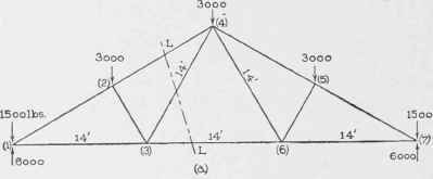
Fig. 16.
10° to the horizontal, | 15 pounds per square foot, | |
20° " " , | 94 " " " " | |
30° " " " , | 32 " " " " | |
40° " " | 36 " " " " | |
50°- | 90° " " " , | 40 " " " " |
The wind pressure on an inclined surface is practically per-pendicular to the surface.
20. Computation of "Apex Loads." The weight of the roof covering including rafters and purlins comes upon the trusses at the points where they support the purlins; likewise the pressure due to wind and snow. Sometimes all the purlins are supported at joints; in such cases the loads mentioned act upon the truss at its joints. However, the roof, snow, and wind loads are always assumed to be applied to the truss at the upper joints of the trusses. This assumption is equivalent to neglecting the bending effect due to the pressure of those purlins which are not supported at joints. This bending effect can be computed separately.
The weight of the truss itself is assumed to come upon the truss at its upper joints; this, of course, is not exactly correct. •Most of the weight does come upon the upper joints for the upper members are much heavier than the lower and the assumption is in most cases sufficiently correct.
Examples. 1. It is required to compute the apex loads for the truss represented in Fig. 10, it being of steel, the roof such that it weighs 15 pounds per square foot, and the distance between adjacent trusses 14 feet.
The span being 42 feet, the formula for weight of truss (Art. 19) becomes
14 X 42 ( 42/25 + 1) = 1,575.84 pounds.
The length 14 scales about 24¼ feet, hence the area of roofing sustained by one truss equals
48½ X 14 = 679 square feet, and the weight of the roofing equals
679 X 15 = 10,185 pounds. The total load equals
1,575.84 + 10,185 = 11,760.84 pounds.
Now this load is to be proportioned among the five upper joints, but joints numbered (1) and (7) sustain only one-half as much load as the others. Hence for joints (1) and (7) the loads equal
1/8 of 11,760 = 1,470, and for (2), (4) and (5) they equal
¼ of 11,760 = 2,940 pounds.
As the weight of the truss is only estimated, the apex loads would be taken as 1,500 and 3,000 pounds for convenience.
2. It is required to compute the apex loads due to a snow load on the roof represented in Fig. 16, the distance between trusses being 14 feet.
The horizontal area covered by the roof which is sustained by one truss equals
42 X 14 = 588 square feet.
If we assume the snow load equal to 10 pounds per horizontal square foot, than the total snow load borne by one truss equals
588 X 10 = 5,880 pounds. This load divided between the upper joints makes
1/8 X 5,330 = 735 pounds at joints (1) and (7); and
¼ X 5,880 = 1,470 pounds at the joints (2), (4), and (5).
3. It is required to compute the apex loads due to wind pressure on the truss represented in Fig. 16, the distance between trusses being 14 ft.
The inclination of the roof to the horizontal can be found by measuring the angle from a scale drawing with a protractor or by computing as follows : The triangle 346 is equilateral, and hence its angles equal 60 degrees and the altitude of the triangle equals
Continue to:
My Books

