346. Plant For Ten-Story Building
Description
This section is from the book "Cyclopedia Of Architecture, Carpentry, And Building", by James C. et al. Also available from Amazon: Cyclopedia Of Architecture, Carpentry And Building.
346. Plant For Ten-Story Building
The plant used by Cramp & Company in constructing a reinforced-concrete building for the Boyertown Burial Casket Company, Philadelphia, will be described, to show the arrangement of the plant rather than the make of the machinery used. The building is 80 feet by 120 feet, and is ten stories high; also, there is a mezzanine floor between the first and second floors. This building is structurally of reinforced concrete, except that the interior columns in the lower floors were constructed of angles and plates and fireproofed with concrete. The power plant for the building is to be located at a level of about seven feet below the basement floor. The hoisting shaft is built in the elevator shaft located in the rear of the building. The hoisting tower is constructed of four 4 by 4-inch corner-posts, and well braced with 2 by 6-inch plank. Two guides are placed on opposite sides; also one on the front, Fig. 146. The front guide was made in lengths equal to the height of different floors of the building. Fig. 146 shows the location of all the machinery, all of which is of the Ransome make. The concrete was discharged directly from the mixer into the bucket, which rested at the bottom of the elevator shaft. At the elevation where it was desirable to dump the concrete, the front slide was taken out, and the concrete was dumped automatically by the bucket tipping forward. The bucket rights itself as soon as it begins to descend.
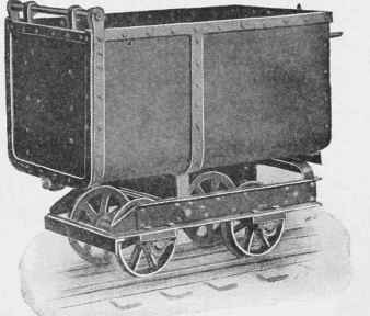
Fig. 145. Steel Body End Dump Car.
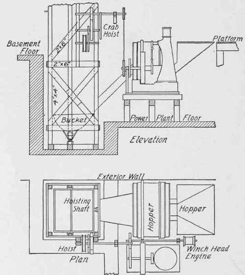
Fig. 146. Concrete Plant for Ten-Story Building.
The capacity of the mixer and hoisting bucket per batch, was 20 cubic feet. A 9 by 9-inch, 20-horse-power vertical engine was used to mix and hoist the concrete, steel, structural steel for columns, and lumber for the forms. A 30-horse-power boiler was used to supply the steam, which was located several feet from the engine, and is not shown in the plan view of the plant. A Ransome friction crab hoist was used to hoist the concrete, and was connected to the engine by a sprocket-wheel and chain. The steel and lumber were hoisted by means of a rope, wrapped three or four times around a winch-head which was on the same shaft as the mixer. The rope extended vertically up from the pulley, through a small hole in the floors, to a small pulley at the height required to hoist the lumber or steel; and then it extended horizontally to another pulley at the place where the material was to be hoisted. The rope descends over the pulley to the ground. A man was stationed at the engine to operate the rope. There were two rope-haulages operated from the pulley on the engine shaft, one being used at a time. On being given the signal, the operator wrapped the rope around the winch-head three or four times, kept it in place, and took care of the rope that ran off the pulley as material was being hoisted.
Wheelbarrows were used in charging the mixer, and hand-carts were used in distributing the concrete. The runways were made by securely fastening two 2 by 10-inch planks together in sections of 12 feet to 16 feet, which were handled by two men. By keeping the runway in good condition, two men were generally able to distribute the concrete, except on the lower floors, and when it was to be transported the full length of the building. The capacity of the carts was 6 cubic feet each. Concrete for the ninth floor was hoisted and placed at the rate of 15 cubic yards per hour.
Continue to:
My Books

