382. Mershon Building
Description
This section is from the book "Cyclopedia Of Architecture, Carpentry, And Building", by James C. et al. Also available from Amazon: Cyclopedia Of Architecture, Carpentry And Building.
382. Mershon Building
Fig. 193 shows the plan of the foundations and the typical layout of the structural members for each floor of a building constructed by Cramp & Company on the south side of Walnut Street, between Ninth and Tenth Streets, Philadelphia. This building was erected during the summer of 1907. It has a frontage of 27 feet on Walnut Street, and a depth of 165 feet on Hutchinson Street, and is eight stories high. It was constructed for manufacturing and storage purposes, and the floors were designed to carry a uniformly distributed live load of 200 pounds per square foot.
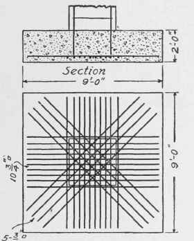
Fig. 194. Detail of Column Footing, Mer-shon Building, Philadelphia, Pa.
At the time that this building was constructed, the Building Code of Philadelphia permitted a working stress of 500 pounds per square inch in compression in concrete, and a tensile strength of 16,000 pounds per square inch in the reinforcing steel. The concrete could be made of any desired proportions that would insure an ultimate strength of 2,000 pounds per square inch. A thickness of 2 inches of concrete was required on the outside of the reinforcing steel in columns, girders, and beams, and 1 inch on the bottom of floor-slabs. The Building Code required that all girders, beams, and slabs should be considered as simple beams supported at the ends, no allowance being made for continuous construction over supports. Owing to the building being only 27 feet wide, interior columns were not required, and therefore footings were needed only along the two sides of the building. The footings along the Hutchinson Street side of the building were designed as isolated footings, as shown in the general plans, and detailed in Fig. 194. But this type of construction could not be used to support the columns of the opposite side of the building, owing to the adjacent property; and therefore a continuous footing was used. This footing, which is 3 feet deep, 6 feet wide, and reinforced with 18 twisted bars 11/8 inches square, is really an inverted beam with a span of 14 feet 9 3/4 inches. In designing this inverted beam, the load was considered the same as the load permitted on the soil, which was 3 1/2 tons per square foot. See Fig. 195.
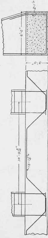
Fig. 195. Details of Continuous Footing, Mershon Building, Philadelphia, Pa.
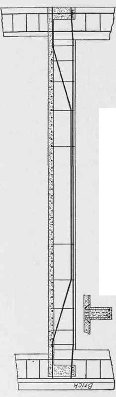
Fig. 196 a. Detail of Beams, Mershon Building, Philadelphia, Pa.
In designing the columns, a working stress of 500 pounds per square inch was allowed for the whole section of the column. The steel reinforcement consists of round bars, handed every 12 inches with a |-inch bar. The area of the longitudinal bars was less than one per cent of the area of the section of the column. The columns decreased in size from 32 by 36 inches in the basement to 12 by 28 inches at the eighth floor.
All the floor-beams were the same size, being 10 inches wide and 18 inches in depth below the slab; but the amount of reinforcement was varied. In the cross-beams between the columns, the reinforcement consisted of 5 twisted bars 1 inch square; but 6 bars 1
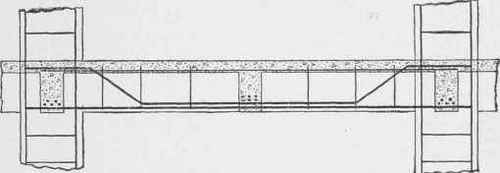
Fig. 196 b. Detail of Girders, Mershon Building.
inch square were required for the cross-beams between the longitudinal beams, as the span was 4 to 5 feet longer for most of the floors. The detail of the beams between the columns is shown in Fig. 196a. The longitudinal beams between the columns were reinforced with 4 twisted bars 1 inch square, the details of which are given in Fig. 1966. The stirrups for all the beams were made of 3/8-inch round steel bars. The beams were connected by a 5-inch slab reinforced with 3/8-inch square bars spaced 5 inches.
Continue to:
My Books

