Forced Blast
Description
This section is from the book "Cyclopedia Of Architecture, Carpentry, And Building", by James C. et al. Also available from Amazon: Cyclopedia Of Architecture, Carpentry And Building.
Forced Blast
This method of heating, in different forms, is used for the warming of factories, schools, churches, theatres, halls or any large building where good ventilation is desired. The air for warming is drawn or forced through a heater of special design, and discharged by a fan or blower into ducts which lead to registers placed in the rooms to be warmed. The heater is usually made up in sections so that steam may be admitted to or shut off from any section independently of the others, and the temperature of the air regulated in this manner. Sometimes a by-pass damper is attached, so that part of the air will pass through the heater and part around or over it; in this way the proportions of cold and heated air may be so adjusted as to give the desired temperature to the air entering the rooms. These forms of regulation are common where a blower is used for warming a single room as in the case of a church or hall; but where several rooms are warmed, as in a schoolhouse, it is customary to use the main or primary heater at the blower for warming the air to a given temperature, (somewhat below that which is actually required) and to supplement this by placing secondary coils or heaters at the bottoms of the flues leading to the different rooms. By means of this arrangement the temperature of each room can be regulated independently of the others. The so-called double duct system is sometimes employed. In this case two ducts are carried to each register, one supplying hot air and the other cold or tempered air, and a damper for mixing these in the right proportions is placed in the flue below the register. Fig. 16 shows a common form of the heater used in connection with a fan; this is encased in heavy sheet iron or brickwork, and is so connected with the fan that the air is drawn or forced through the spaces between the hot pipes and thus becomes heated. Fig. 17 represents the usual form of fan wheel used for heating and ventilating work; this is enclosed in a steel plate casing with inlet openings at the sides and a discharge outlet at the outer edge of the fan. A common arrangement of fan and heater is shown in Fig. 18. The arrows indicate the cold air entering the heater and the discharge from the fan is through the circular opening at the top of the casing. This fan is shown as being driven by a direct connected engine.
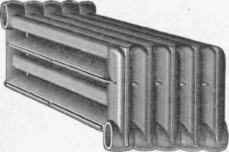
Fig. 15.
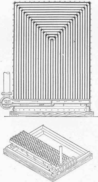
Fig.16.
Electric motors and steam engines are both used for this purpose and may be either belted or direct connected.
Fig. 19 shows a fan and heater arranged for a double duct system. A portion of the air passes through the heater, the top of which can be seen where the casing is broken away; the remainder of the air passes partly through, and partly over the heater, depending upon the position of the by-pass damper above. The temperature of the air in the upper duct is therefore less than that in the lower, and the two can be mixed at the registers as required. In Fig. 20 is shown a type of fan called the "cone fan." This is usually placed in an opening in a brick wall and discharges air from its entire perimeter into a room called a "plenum" chamber, with which the various distributing ducts connect.
Continue to:
My Books

