Method Of Planning A Wiring Installation. Part 2
Description
This section is from the book "Cyclopedia Of Architecture, Carpentry, And Building", by James C. et al. Also available from Amazon: Cyclopedia Of Architecture, Carpentry And Building.
Method Of Planning A Wiring Installation. Part 2
The chase, if possible, should be continuous from the cellar to the roof, or as far as needed. This is necessary in order to avoid unnecessary bends or elbows, which are objectionable for many reasons.
In similar manner, the location of cut-out cabinets or distributing centers should fulfil the following requirements: 1. They should be accessible at all times.
2. They should be placed sufficiently close together to prevent the circuits from being too long.
3. Do not place them in too prominent a position, as that is objectionable from the Architect's point of view.
4. They should be placed as near as possible to the rising chases, in order to shorten the feeders and mains supplying them.
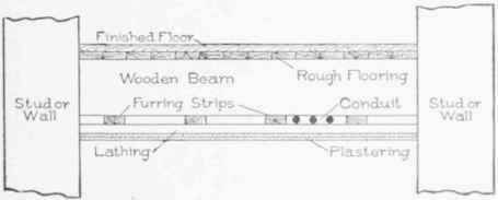
Having determined the system and method of wiring, the location of outlet and distributing centers, the next step is to lay out the branch circuits supplying the various outlets. Before starting to lay out the branch circuits, a drawing showing the floor construction, and showing the space between the top of the beams and girders and the flooring, should be obtained from the Architect. In fireproof buildings of iron or steel construction, it is almost the invariable practice, where the work is to be concealed, to run the conduits over the beams, under the rough flooring, carrying them between the sleepers when running parallel to the sleepers, and notching the latter when the conduits run across them (see Fig. 31). In wooden frame buildings, the conduits run parallel to the beams and to the furring (see Fig. 32); they are also sometimes run below the beams. In the latter case the beams have to be notched, and this is allowable only in certain places, usually near the points where the beams are supported. The Architect's drawing is therefore necessary in order that the location and course of the conduits may be indicated on the plans.
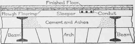
Fig. 31. Running Conductors Concealed under Floor in Fireproof Building.
The first consideration in laying out the branch circuit is the number of outlets and number of lights to be wired on any one branch circuit. The Rules of the National Electric Code (Rule 21-D) require that "no set of incandescent lamps requiring more than 660 watts, whether grouped on one fixture or on several fixtures or pendants, will be dependent on one cut-out." While it would be possible to have branch circuits supplying more than 660 watts, by placing various cut-outs at different points along the route of the branch circuit, so as to subdivide it into small sections to comply with the rule, this method is not recommended, except in certain cases, for exposed wiring in factories or mills. As a rule, the proper method is to have the cut-outs located at the center of distribution, and to limit each branch circuit to 660 watts, which corresponds to twelve or thirteen 50-watt lamps, twelve being the usual limit. Attention is called to the fact that the inspectors usually allow 50 watts for each socket connected to a branch circuit; and although 8-candle-power lamps may be placed at some of the outlets, the inspectors hold that the standard lamp is approximately 50 watts, and for that reason there is always the likelihood of a lamp of that capacity being used, and their inspection is based on that assumption. Therefore, to comply with the requirements, an allowance of not more than twelve lamps per branch circuit should be made.
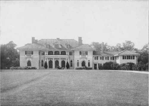
RESIDENCE OF B. J. ALLAN, BEVERLY, MASS. Guy Lowell. Architect. Boston. Mass.
In ordinary practice, however, it is best to reduce this number still further, so as to make allowance for future extensions or to increase the number of lamps that may be placed at any outlet. For this reason, it is wise to keep the number of the outlets on a circuit at the lowest point consistent with economical wiring. It has been proven by actual practice, that the best results are obtained by limiting the number to five or six outlets on a branch circuit. Of course, where all the outlets have a single light each, it is frequently necessary for reasons of economy, to increase this number to eight, ten, and, in some cases, twelve outlets.
We have already referred to the location of the wires or conduits. This question is generally settled by the peculiarities of the construction of the building. It is necessary to know this, however, before laying out the circuit work, as it frequently determines the course of a circuit.
Now, as to the course of the circuit work, little need be said, as it is largely influenced by the relative position of the outlets, cutouts, switches. etc. Between the cut-out box and the first outlet, and between the outlets, it will have to be decided, however, whether the circuits shall run at right angles to the wall of the building or room, or whether they shall run direct from one point to another, irrespective of the angle they make to the sleepers or beams. Of course, in the latter case, the advantages are that the cost is somewhat less and the number of elbows and bends is reduced. If the tubes are bent, however, instead of using elbows, the difference in cost is usually very slight, and probably does not compensate for the disadvantages that would result from running the tubes diagonally As to the number of bends, if branch circuit work is properly laid out and installed, and a proper size of tube used, it rarely happens that there is any difference in "pulling" the branch circuit wires. It may happen, in the event of a very long run or one having a large number of bends, that it might be advisable to adopt a short and most direct route.
Continue to:
My Books

