Practical Miter Cutting. Part 10
Description
This section is from the book "Cyclopedia Of Architecture, Carpentry, And Building", by James C. et al. Also available from Amazon: Cyclopedia Of Architecture, Carpentry And Building.
Practical Miter Cutting. Part 10
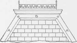
Fig. 329.
Before the patterns can be obtained, a developed surface of the mansard must be draw n. Therefore, from B (Fig. 330), drop a vertical line as B J, intersecting the line C K at J. Now take the distance of B C, and place it on a vertical line in Fig. 331, as shown by B C '. Through these two points draw the horizontal lines B A and C K as shown. Take the projection J to C in Fig. 330, and place it as shown from C1 to C in Fig. 331, and draw a line from C to B. Then will A B C K be the developed surface of A B C K in Fig. 330.
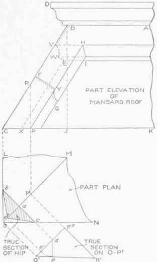
Fig. 330.
As both the profiles B V W E and F Y G are similar, take a tracing of either, and place it as shown by D and D1 respectively in Fig. 331.
Divide both into the same number of equal spaces, as shown. Bisect the angle A B C by establishing a and b, and, using these as centers by describing arcs intersecting at c; then draw d B, which represents the miter-line. Through the points in D and D1, draw lines parallel to their respective moulds, as shown, intersecting the miter-line B d and the base-line C C1.
For the pattern for the hip, draw any line, as E F, at right angles to B C, upon which place twice the stretchout of D, as shown by the divisions 6 to 1 to 6 on EF. Through these divisions draw lines at right angles to E F, intersecting similarly numbered lines drawn at right angles to B C from the divisions on B d and C C1. Trace a line through the points thus obtained. Then will G H J L be the pattern for the hip ridge.
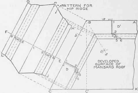
Fig. .3.31.
When bending this ridge in the machine, it is necessary to know at what angle the line 1 in the pattern will be bent. A true section must be obtained at right angles to the line of hip, for which proceed as shown in Fig. 330. Directly in line with the elevation, construct a part plan L M N O, through which, at an angle of 45 degrees (because the angle L O N is a right angle), draw the hip line O M. Establish at pleasure any point, as P1 on O M, from which erect the vertical line into the elevation crossing the base-line CKat P and the ridge-line C B at R. Parallel to O M in plan, draw O1 P2, equal to O P1, as shown. Extend P1 P2 as P2 R1, which make equal to PR in elevation.
Draw a line from R1 to O1. Then O1 R1 P2 represents a true section on OP1 in plan. Through any point, as a, at right angles to OM, draw bc, cutting L O and ON at b and c respectively. Extend b c until it intersects O1 P2 at d. From d, at right angles to O1 R1, draw the line d e. With d as center, and de as radius, draw the arc e e', intersecting O1 P2 at e', from which point, at right angles to OM in plan, draw a line intersecting OM at e". Draw a line from b to e" to c, which repre sents the true section of the hip after which the pattern shown in Fig. 331 is formed.
The pattern for the deck mould D B in Fig. 330 is obtained in the same way as the square miter shown in Fig. 277; while the pattern for the apron D' in Fig. 331 is the same as the one-half pattern of the hip ridge shown by n H 16.
In Fig. 332 is shown a front elevation of an eye-brow dormer. In this view A B C represents the front view of the dormer, the arcs being struck from the center points D, E, and F. A section taken on the line H J in elevation is shown at the right; L M shows the roof of the dormer, indicated in the section by N; while the louvers are shown in elevation by O P and in section by R T.
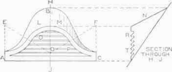
Fig. 332.
In Fig. 333 is shown how to obtain the various patterns for the various parts of the dormer. ABC represents the half-elevation of the dormer, and EFG a side view, of which EG is the line of the dormer, E F that of the roof, and GF the line of the pitched roof against which the dormer is required to miter.
The front and side view being placed in their proper relative positions, the first step is to obtain a true section at right angles to EF.
Proceed as follows : Divide the curve A to B into a number of equal spaces, as shown from 1 to 9. At right angles to A C, and from the figures on A B, draw lines intersecting E G in side view as shown.
From these intersections, and parallel to EF, draw lines intersecting the roof-line GF at 15, 25, 35, etc. Parallel to EF, and from the pointG, draw any line indefinitely, as G H. At right angles to EF, and from the point E, draw the line EH, intersecting lines previously drawn, at 11, 21, 31, etc., as shown. Now take a duplicate of the line E H, with the various intersections thereon, and place it on the center line AC extended as KJ. At right angles to KH, and from the figures 12, 22, 32 etc., draw lines, which intersect with those of similar numbers drawn at right angles to CB, and from similarly numbered points on the curve A B. Trace a line through the points of intersection thus obtained.
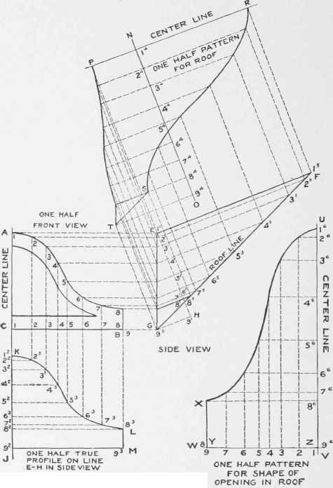
Fig. 333.
Then KLMJ will be one-half the true profile on the line E H in side view, from which the stretchout will be obtained in development of the pattern.
For the pattern for the roof of the dormer, draw at right angles to EF in side view the line N O, upon which place the stretchout of one-half the true profile on the line EH, as shown by the small figures 14, 24, 34, etc. Then, at right angles to N O, and through the figures, draw lines, which intersect with those of similar numbers drawn at right angles to EF from intersections on EG and GF. Trace a line through the points thus obtained. Then will PRST represent one-half the pattern for the roof.
To obtain the pattern for the shape of the opening to be cut into the roof, transfer the line GF, with the various intersections thereon, to any vertical line, as U V, as shown by the figures 16, 26, 36, etc. In similar manner, transfer the line CB in front view, with the various intersections on same, to the line ZW, drawn at right angles to UV, as shown by the figures 1, 2, 3, etc.
Continue to:
My Books

