The Planes Of Projection. Part 2
Description
This section is from the book "Cyclopedia Of Architecture, Carpentry, And Building", by James C. et al. Also available from Amazon: Cyclopedia Of Architecture, Carpentry And Building.
The Planes Of Projection. Part 2
A line drawn from the horizontal projection of a to the hori-zontal projection of the station point will represent the horizontal projection of the visual ray, which passes through the point a. In Fig. 8, this horizontal projection is represented by the line drawn on the plane of the horizon from aH to SPH. Thus we have, drawn upon the planes of projection, the vertical and horizontal projections of the point a, and the vertical and horizontal projections of the visual ray passing between the point a and the station point.
35. We must now find the intersection of the visual ray with the picture plane. This intersection will be a point in the picture plane. It is evident that its vertical projection must coincide with the intersection itself, and that its horizontal projection must be in 1IPP (§ 32). But this intersection must also be on the visual ray through the point a, and consequently the horizontal projection of this intersection must be on the horizontal projection of the visual ray. Therefore, the horizontal projection of this intersection must be the point mH, where the line between SPH and aH crosses HPP. The vertical projection of this intersection must be vertically in line with this point, and on the line drawn between SPV and av, and hence at mV. Since the vertical projection of the intersection coincides with the intersection itself, aP (coincident with mV) must be the perspective of the point a.
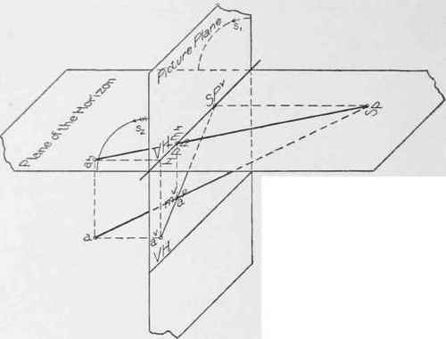
Fig. 8.
Fig. 9.
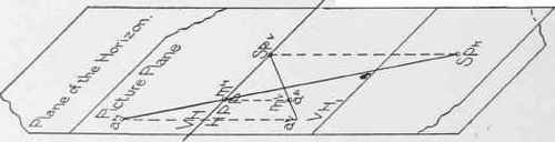
Fig. 9a.
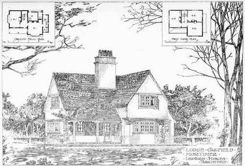
LODGE OAKFIELD MORTIMER, ENGLAND.
Leonard Stokes, Architect.
This Design is Adaptable to an American Cottage.
Repriprinted by permission from"Modern Cottage Architecture," John Lane Co . Publishers
36. This is the method of finding the perspective of any point, having given the vertical and horizontal projections of the point and of the station point. The method may be stated briefly as follows : -
Draw through the horizontal projection of the point and the horizontal projection of the station point, a line representing the horizontal projection of the visual ray, which passes through the point. Through the intersection of this line with HPP, draw a vertical line. The perspective of the point will be found where this vertical line crosses the vertical projection of the visual ray, drawn through SPV and aV.
37. It would evidently be inconvenient to work upon two planes at right angles to one another, as shown in Fig. 8. To avoid this, and to make it possible to work upon a plane surface, the picture plane (or vertical coordinate) is supposed to be revolved about its intersection with the plane of the horizon, until the two coincide and form one surface. The direction of this revolution is indicated by the arrows sl and s2. After revolution, the two coordinate planes will coincide, and the vertical and horizontal projections overlap one another, as indicated in Fig. 9.
It will be noticed that the coincidence of the two planes in no way interferes with the method given in § 36, of finding the perspective (ap) of the point a, from the vertical and horizontal projections of the point. Thus, the horizontal projection of the visual ray through the point will be seen, drawn from SPH to aH, and intersecting HPP in the point mH. The vertical projection of the visual ray through the point will be seen passing from SPV to aV. And aP is found upon the vertical projection of the visual ray, directly under mH.
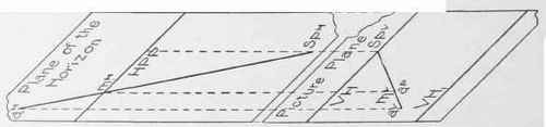
It will readily be understood that in a complicated problem, the overlapping of the vertical and horizontal projections might result in some confusion. It is, therefore, usually customary, after having revolved the two coordinate planes into the position shown in Fig. 9, to slide them apart in a direction perpendicular to their line of intersection, until the two planes occupy a position similar to that shown in Fig. 9a.
38. It will be remembered from the course on projections which the student is supposed to have taken, that horizontal projections must always be compared with horizontal, and never with vertical projections, and that in the same way, vertical projections must always be compared with vertical, and never with horizontal projections. It is evident that in sliding the planes apart, the relations between the projections on the vertical plane will not be disturbed, nor will the relations between the projections on the horizontal plane, and consequently it will make no difference how far apart the two coordinate planes are drawn, provided that horizontal and vertical projections of the same points are always kept in line. Thus, in Fig. 9a, it will be seen that in drawing the planes apart,aV has been kept in line with aH, mV with mH, SPV with SPH, etc.
39. It will be observed that in sliding the planes apart, their line of intersection has been separated into its two projections ( §§ 31 and 32). HPP, being on the plane of the horizon or horizontal coordinate, is the horizontal projection of the intersection of the two planes, while VH, being on the picture plane or vertical coordinate, is the vertical projection of the intersection of the two planes. In the original position of the planes (Fig. 9) these two projections were coincident. The distance between HPP and VH always represents the distance through which the planes have been slid. This distance is immaterial, and will have no effect on the perspective drawing. VH 1 represents the vertical trace of the plane of the ground.
In this figure, as in the case of Fig. 9, the student should follow through the construction of the perspective of the point a, applying the method of § 36.
40. Fig. 10 shows the position of the two coordinate planes and of the plane of the ground, as they are usually represented on the drawing board in making a perspective drawing. It is essentially the same thing as Fig. 9a, except that the latter was shown in oblique projection in order that its development from the original position of the planes (Fig. 8) might be followed more readily. The two coordinate planes are supposed to lie in the plane of the paper.
Continue to:
My Books

