Vanishing Points Of Oblique Lines. Continued
Description
This section is from the book "Cyclopedia Of Architecture, Carpentry, And Building", by James C. et al. Also available from Amazon: Cyclopedia Of Architecture, Carpentry And Building.
Vanishing Points Of Oblique Lines. Continued
In the case of the line fd, the diagram shows the point d to be farther behind the picture plane than the point f, while the elevation shows the point d to be lower than the point /. Therefore the line must vanish downward, and its vanishing point be found be'ow VII.
If one horizontal projection of a line, as shown by the diagram, is parallel to HPP, the line itself is parallel to the picture plane, and the perspective of its vanishing point cannot be found within finite limits (§ 54, note). The perspective projections of such a system of lines will show the true angle which the elements of the system make with the horizontal coordinate.
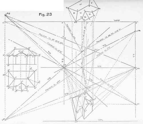
70. The construction for the vanishing points in Fig. 23 is shown by dot and dash lines.
The vanishing points for the two systems of horizontal lines have been found at vab and vad respectively, as in the preceding problems.
Next consider the line af. The first step is to construct a revolved plan and elevation of this line to agree with the position of the diagram. Revolve the horizontal projection (aHfH) of the line in the given plan about the point fH, until it is parallel to the line af in the diagram. During this revolution, the point fH remains stationary, while the point ah describes a horizontal arc, until ahfh has revolved into the position shown by the red line aHfH, which is parallel to the line af in the diagram. The vertical projection aYfv must, of course, revolve with the horizontal projection. The point fv remains stationary, while the horizontal arc described by the point a shows in vertical projection as a horizontal line. At every point of the revolution the vertical projection of the point a must be vertically in line with its horizontal projection. When ah has reached the position a1,H, av will be vertically above a1h at the point a1v, and a1vf v will be the revolved elevation of the line.
We now have the vertical and horizontal projections (a1vfv and ah1fh) of an element of the system to which the roof line, represented in the diagram by af belongs. The vanishing point of this system may be determined as in Problem III. Draw through SPH a line parallel to a1fH (or af in the diagram), representing the horizontal projection of the visual element of the system. Draw through SPV a line parallel to a1vfv, representing the vertical projection of the visual element of the system. The visual element, represented by the two projections just drawn, pierces the picture plane at vaf (§ 45, note), giving the perspective of the vanishing point for the roof line, represented by af in the diagram.
In a similar manner the vanishing point for the roof line, represented in the diagram by bg, may be determined. First find, from the given plan and elevation of the object, a revolved plan and elevation of bg, to agree with the position of the line in the diagram. Revolve bhgh in the given plan about the point gH, until it is parallel to bg in the diagram, and occupies the position indicated by the line b1hgh. The corresponding revolved elevation is represented by the red line b1vgv.
b1Hgh and blhgv now represent respectively the horizontal and vertical projections of an elemeut of the system to which the roof line, represented by bg in the diagram, belongs. The vanishing point of this system can be found by Problem III. Through SPH draw a line parallel to b1h gh (or bg in the diagram), representing the horizontal projection of the visual element of the system ; and through SPV draw a line parallel to blygy, representing the vertical projection of their visual element. The visual element, represented by these two projections, pierces the picture plane at vbg, giving the perspective of the vanishing point of the roof line, represented in the diagram by the line bg.
By a similar process, hHk1h and hv k 1are found to represent-respectively the horizontal and vertical projections of an element of the system to which belongs the roof line represented in the diagram by the line hk. The perspective of the vanishing point of this line has been found at vhk.
vaf, vbgt and vhk have all been found to lie above VH (§ 51. note).
71. vfd, vgc, and vklre found exactly as were vaf, vbg, and vhk; but, as the systems to which they belong vanish downward, they will lie below VH (§ 51, note).
Thus, flhd1h and fvd1v are respectively the horizontal and vertical projections of an element of the system represented by fd in the diagram. A line drawn through SPH, parallel tofH d1h(or fd in the diagram), will intersect HPP in the point to. A vertical line through w will intersect a line through SPV parallel to fyd1v, below VH.
72. Having found the perspectives of these vanishing points, the perspectives of the vanishing traces of all the planes in the object should be drawn as a test of the accuracy with which the vanishing points have been constructed. The roof planes in the house are lettered with the capital letters M, N, O, P, etc., on the diagram.
Proposed House for- Mrs C Birton Ellis A.R. Ellis. Archt boston.
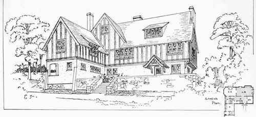
PROPOSED HOUSE FOR MRS. C. BIRTON ELLIS, SENECA LAKE, N. Y.
A. Raymond Ellis, Architect, Hartford, Conn. An Interesting Example of Plaster and Half-Timber Construction. Cost, about $14,000. For Plan, See Following Page; for Elevations, See Page 138.
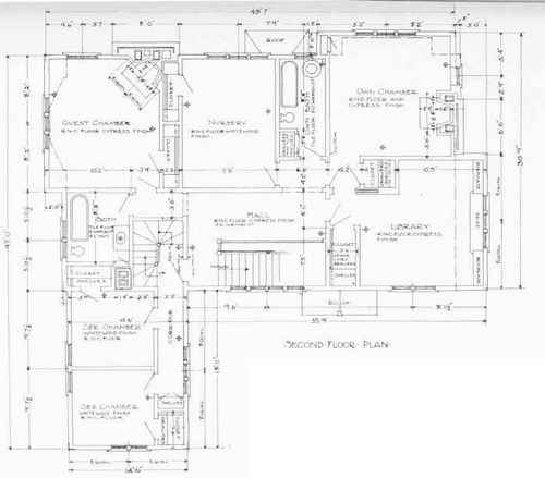
NOTE - FIGURES ARE FROM FACE OF STVD1 AND CENTRE of PARTITIONS-
House for Mrs -C-B1RTON-ELLIS- AT-SENECALAKE-N-Y- A R ELLIS- ARCHITECT- BOSTON.
SECOND-FLOOR PLAN OF HOUSE F0RMRS. C. BIRTON ELLIS, SENECA LAKE, N. Y.
A. Raymond Ellis, Architect, Hartford, Conn. Perspective View Shown on Preceding Page. For Elevations, See Page 138.
The plane O contains the lines af, ad, and fd. Therefore, the vanishing trace (TO) of the plane must be a straight line passing through the three vanishing points, vaf, vad, and vtd (§ 24 d). If all three of these vanishing points do not lie in a straight line, it shows some inaccuracy, either in draughting or in the method used in finding some of the vanishing points. The student should not be content until the accuracy of his work is proved by drawing the vanishing trace of each plane in the object through the vanishing points of all lines that lie in that plane.
The plane M contains the lines fd, go, and dc. The last line belongs to the system ab, and hence its vanishing point is vab. The vanishing trace (TM) of the plane M must pass through vtd, vge and vab.
Similarly, the vanishing trace (TP) of the plane P must pass through vgc, vbg, and vad TN must pass through vab, vaf, and vbg. TQ must pass through vhk and vad. TR must pass through vkl and vad.
73. The vanishing trace of a vertical plane will always be a vertical line passing through the vanishing points of all lines which lie in the plane. Therefore, the vanishing trace of the vertical planes in the house that vanish towards the left will be represented by a vertical line (TS) passing through vdd.
The vanishing trace of the vertical planes of the house that vanish towards the right will be represented by a vertical line (TT) passing through vab. As the vertical plane which forms the face of the porch belongs to this system, and as this plane also contains the lines hk and kl, TT will be found to pass through Vhk and vkl as well as v:ab.
74. It will be noticed that the vanishing points for the lines mn and on have'not been found. These vanishing points might have been found in a manner exactly similar to that in which the other vanishing points were found, or they may be determined now, directly from the vanishing traces already drawn, in the following manner: -
The line mn is seen to be the line of intersection of the two planes N and Q. Therefore (§ 24 e) vmn must lie at the intersection of TN and TQ.
For a similar reason, von must lie at the intersection of TN and TR. TN and Tit do not intersect within the limits of the plate, but they are seen to converge as they pass to the left, and, if produced in that direction, would meet at the vanishing point for the line on.
75. Having found vab, vad, wbg, and vfd, TN could have been drawn through vab and vhK; and TO could have been drawn through vad and vfd. As af is the intersection of the two planes N and O, Vaf could have been found at the intersection of TN and TO without actually constructing this vanishing point.
Similarly, vgc could have been determined by the intersection of TM and TP.
By an examination of the plate, the student will notice that the vanishing point for each line in the object is formed at the intersection of the vanishing traces of the two planes of which the line forms the intersection. Thus, the line ad forms the intersection between the plane O and the left hand vertical face of the house. vad is found at the intersection of TO and TS.
The line fg, which forms the ridge of the roof, is the intersection of the planes M and N. The vanishing point for fg is vab, and TM and TN will be found to intersect at vab. vhk is found at the intersection of TQ and TT, Vkl is found at the intersection of TR and TT, etc.
It will be noticed also that the two lines hk and kl lie in the same vertical plane, and make the same angle with the horizontal, one vanishing upward, and one vanishing downward. Since both lines lie in the same vertical plane, both of their vanishing points will be found in the vertical line which represents the vanishing trace of that plane. Also, since both lines make equal angles with the horizontal, the vanishing point of the line vanishing upward will be found as far above VH as the vanishing point of the line vanishing downward is below VH.
In a similar way, the line bg vanishes upward, and the line fd vanishes downward; each making the same angle with the horizontal (as shown by the given plan and elevation). These two lines do not lie in the same plane, but may be said to lie in two imaginary vertical planes which are parallel to one another. Their vanishing points will be seen to lie in the same vertical line, vbgs being as far above VH as vfd is below it.
As a general statement, it may be said that if two lines lie in the same or parallel vertical planes, and make equal angles with the horizontal, one vanishing upward and the other van= ishing downward, the vanishing points for both lines will be found vertically in line with one another, one as far above VH as the other is below it.
This principle is often of use in constructing the vanishing point diagram. Thus, having found Vhk, vkl could have been determined immediately by making it lie in a vertical line with vhk, and as far below VH as Vhk is above it.
Continue to:
My Books

