Chapter VII. Cast-Iron Columns
Description
This section is from the "Architectural Iron And Steel, And Its Application In The Construction Of Buildings" book, by WM. H. Birkmire.. Also see Amazon: Architectural Iron And Steel, And Its Application In The Construction Of Buildings.
Chapter VII. Cast-Iron Columns
102. Column Shafts Ornamented
In almost all modern buildings cast-iron columns are used, not only for their strength in the support of the superstructure, but as a means of decoration, being ornamented to suit the style of the building and the taste of the architect.
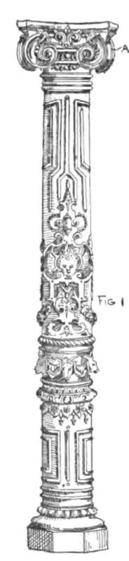
The shaft of the column is cast without capitals, bases and other ornaments, these being cast separately and fitted to the shaft when the column is turned off, or fitted to the column when placed in the building. The plain and moulded bands if not undercut are frequently cast with the shaft, serving as a good guide and rest for the other ornamental parts.
103. Capitals
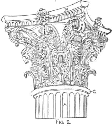
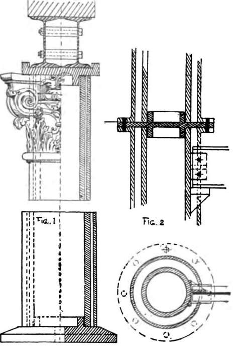
The capital of column if ornamented with leaves, etc., as Fig. 2, is constructed of a 3/16-inch-thick shell bell; the leaves are cast singly and screwed to the bell.
The abacus B is cast in two pieces or halves 3/16 inch thick. The entire capital is fitted up completely at the works and taken apart in halves, and placed over and secured to column when this has been set in place.
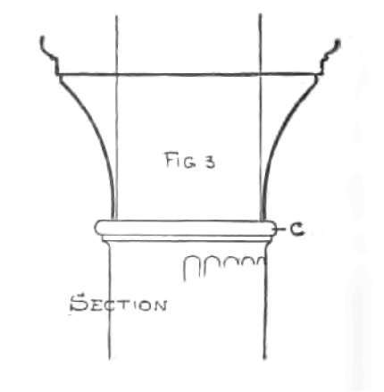
The shaft of column above neck moulding C, Fig. 3, should be from 3/8 to 1/2 inch less than the diameter of body, to admit of the bell being placed on it without showing any bulging of the bottom of capital.
To give a rich bold relief to the ornamentation on Fig. 1, the work will require to be well undercut.
104. Cast-Iron Column Connection
For connecting with the floor beams and with each other cast-iron columns make the simplest, cheapest and best finished connections for buildings. The single beam has for its bearing a small bracket at D, and for connection a lug at C, with a stiffening web (E) at side.
For the double-beam girder a lug separator is cast on the column, fitting closely to the webs and flanges of same.
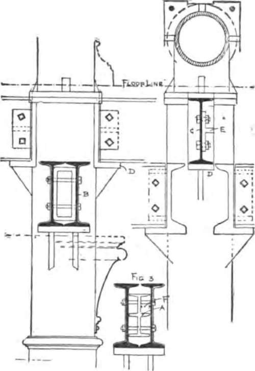
Fig. 3 shows another kind of lug, but one not so good as the former, for the reason that if there is any tendency to pull the girder from column, the bolts will be apt to bend at distance F.
The lugs and brackets should not be less in thickness than the body of column; and allow 5 to 6 inches projection for brackets and 4 inches for lugs, with not less than two bolts in each lug.
105. Holes Drilled
It is better practice to drill all holes in flanges and lugs. Oval holes in lugs are of no use when a good tight connection is required.
In connecting the columns of a story with those of the one below, the floor line should be considered; otherwise the bolt heads would appear above the floor, unless a large shell base be required. In that case it would be well to make the joint of columns at the finished floor level, especially if floor beams are connected to the columns on all sides; otherwise there would be little flange left for bolts.
As shown in plate, the upper column has brackets to reinforce the flange; the lower column is made thicker on the inside, to bring the body of metal in the column below under that of the column above. But plates between flanges serve a better purpose. The flanges and plates should be planed true and columns set plumb, as shimming (by placing small thin plates to make up difference) or wedging (by driving wedges under flange) may cause a rupture in column by the concentrated weight which would naturally pass to the point of column bearing.
106. Column Flanges
Circular and square flanges are used for connecting columns together. The diameter of bolts and heads often determines the projection of flange. If squarehead bolts are used, the flanges should project not less than three inches from shaft.
If hexagon-head bolts are used, the flanges may project a trifle less than three inches.
107. Fire-Proof Column
Fire-Proof Column is a supporting column of cast iron, with a cast-iron shell covering, and an air space of one to three inches, sometimes filled with some incombustible material, but more frequently left entirely clear.
The inner column should be of sufficient strength to alone sustain the weight to be imposed.
In connecting and resting an upper on a lower column, a plate should be placed between the two as shown at Fig. 2; a floor beam or girder also being shown below the connection, secured to a lug and resting on a bracket cast on the column.
If a small beam, with a light load, is to be connected, a bracket cast on the outer shell will be sufficient for its support, a 3/4-inch-thick shell being as light a column (over 9 inches in diameter) that should be cast for supporting any weight.
108. Dowel Columns
For buildings where the floor beams and girders are of wood, the columns for their support are cast as shown. The portion of column at girder is cast similar to the dowel A; the girder being cut to this shape with 2 inches at least on each side of the flat portion of dowel, and resting on a cast-iron plate made the full width of girder, with additional lips on each side for holding the girder in place.
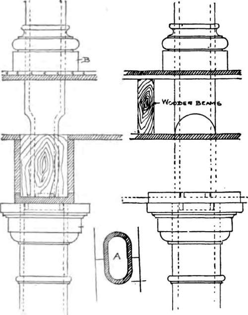
This manner of connecting columns is not an example of good construction, as the upper column is prevented from moving from its position only by the wooden girder and the raised socket cast on the plate and entering the dowel. For a better and safer connection with wooden girders, see "Flitch-plate Girders".
Continue to:
My Books

