Types Of Foundations. Part 3
Description
This section is from the book "Modern Buildings, Their Planning, Construction And Equipment Vol1", by G. A. T. Middleton. Also available from Amazon: Modern Buildings.
Types Of Foundations. Part 3
A formula which seems to give a satisfactory result while it agrees with practically every building which has not settled to any appreciable extent is given by Trautwine -
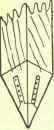
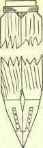
Fig. 65.
Safe load in tons
Where W, h, and d have the same values as in Major Sanders' formula.
A factor of safety of 2 is used when the piles are driven in firm soils, but this should be increased to 6 in muddy or marshy soils.
Of course, a trial pile must be driven to find the values in the above formulas; but it is generally better to disregard formulae and test the pile with a load.
When the piles have been driven to the required depths they are all sawn off level below the ground line, and horizontal timbers called sleepers, of the same size as the piles, are notched over and thoroughly spiked to them. Cross-pieces of the same section as-the sleepers are then notched over and spiked to these, and the whole framework is filled in with concrete, as shown in Fig. 66. This method of notching is objectionable in very heavy buildings, as the fibres of the sleepers crush where they bear upon the piles.
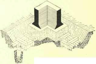
Fig. 66.
Sometimes, instead of cross-pieces, planks are laid close together across the sleepers, and on these the concrete bed is formed; while sleepers are often avoided altogether, the piles being left projecting a short distance from the bottom of the trench, and the concrete being filled in round them.
The custom of having the concrete in contact with wood is a bad one, as it causes the wood to decay, especially when the concrete surrounds it; and this fact has led to the practice of placing large slabs of stone upon the heads of the piles to form a base on which to raise the concrete. When such slabs are used care should be taken that all four corners of each, not only rest upon but bear thoroughly upon every point of the head of a pile.
(B) Bearing Piles
When a soft soil, not greater than 40 feet deep, overlies a hard firm soil, piles are driven down through the soft into the hard soil, or in the case of a very hard substratum such as rock the feet of the piles rest upon the rock, and perform to a certain extent the function of a column, save that lateral support is afforded by the soil, which of course varies with its nature. Such piles are called bearing piles.
The Bearing Power of Bearing Piles is sometimes calculated by means of Major Sanders' formula, but this should be avoided, as the formula was never intended to apply to bearing piles, the experiments upon which the formula is based having been carried out upon friction piles.
Professor Rankine's rule for the safe bearing capacity of piles is perhaps most frequently used, and is as follows: -
"In piles driven till they reach the firm ground, 1000 lbs. per square inch of area of head.
" In piles standing in soft ground by friction, 200 lbs. per square inch of head."
These rules apply to piles which are not driven more than \ inch by 30 blows of a ram weighing 800 lbs., and falling 5 feet at each blow.
The best plan is to drive a test pile and load it until sinking takes place, and to allow a certain factor of safety according to the nature of the soil.
Fig. 67 shows an angle of a building carried upon bearing piles. The piles are driven in rows at right angles to the walls, and a platform is built upon them as described in connection with friction piles.
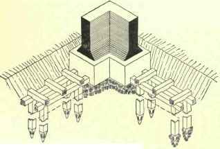
Fig. 67.
(C) Sheet Piles
When a building is to be erected upon a soft soil, sand, loose gravel, or mud, the whole site is sheathed in piles to confine the soil, so that it may act as a homogeneous block, being unable to escape as it would certainly do were it not confined.
The method of sheet piling is as follows: The whole site is excavated to a depth of 2 feet or more. Piles, usually 9 inches square and upwards, and grooved on two sides, are driven in all round the site at intervals of from 6 to 10 feet. These piles, which are called Guide Piles, are left projecting about 2 feet from the bottom of the excavation, and two pairs of timbers, called Wales or Waling Pieces, usually 9 by 6 inches, are notched and bolted on to both sides of them, one pair at the bottom of the excavation and the other pair at the head of the pile as shown in Fig 68.
At the angles of a building a wale is notched and bolted to the corner guide pile and a cleat is bolted to one face to form a fixing for the other wale.
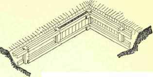
Fig. 68.
Sheet piles, from 8 to 11 inches wide and from 2 1/2 to 4 inches thick, are driven between these waling pieces, starting at a guide pile. These sheet piles are sharpened, as shown in Fig. 69, and shod with sheet iron, as at A, Fig. 69, or with cast or malleable-iron blocks, as shown at B in the same Figure. The sloped foot of the sheet pile causes it to press against the pile last driven. The edges of sheet piles are bird's-mouthed or grooved and tongued so that they may form a closed joint when driven into position, as shown in Fig. 70.
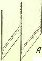
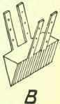
Fig. 69.
When the piling is completed the site is covered with a bed of concrete, to prevent the soil from oozing up under the load.
Continue to:
My Books

