Rivets, Riveting And Pins. Part 13
Description
This section is from the book "Safe Building", by Louis De Coppet Berg. Also available from Amazon: Code Check: An Illustrated Guide to Building a Safe House.
Rivets, Riveting And Pins. Part 13
By referring to a table of areas of circles, or by calculation we find ing-moment. We have marked along the pin, Figure 187, the thicknesses of heads, the length of pin required being 5 1/2", to this must be added the head and nut and also sufficient for strut D (5/8") which we remember did not come into the calculation along line A E (Figure 182.)
Design for largest Strain first,
Shearing strain too great. ' that for an area of cross-section of 8 square inches we require a diameter of 3 3/16". This is a larger pin than we want to use and besides seems a very large pin for the strains; it is evident, therefore, that our heads are badly arranged along the pin ; we will decide, therefore, to divide the rods E and C each in two parts, making each head one-half the thickness as above found, and arrange them as shown in Figure 187.
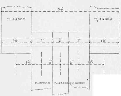
Fig. 187.
Now the safe cross-shearing on our pin (2 3/4") for single-shear would be from Table XXXIX = 47600 pounds, we pass along horizontal line 2 3/4" till we strike iron single-shear curve and then pass upward about four-fifths way between the third and fourth vertical lines to the right of 40000; as each space is evidently 2000 pounds, we should have 400000 +3 4/5. 2000 = 47600 pounds. By calculation we should have had area of 2 3/4" circle = 5,939 square inches, therefore safe (single) cross-shearing see Formula (7) =5,939.8000= 47512 pounds. The greatest cross-shearing strain on the pin with arrangement as shown in Figure 187 is 44000 pounds, and is between the heads E and C (or E, and C, ). so that we need not fear shearing.
The shearing area of pin being all right we now consider the bend-
Shearing from Table XXXIX.
Immediately under the pin, Figure 187, we have marked the distances from centre to centre of heads, which are, of course, the distances we consider when calculating the bending-moment. Accordingly our pin becomes a circular wrought-iron beam of 2 3/4" diameter, with a span or length of 4 1/8" and supported at both ends by forces E and E1. The beam is loaded with the forces C, C1 and B as shown in Figure 187.
The greatest bending-moment will be at the centre (See p. 51, Vol. I), and will be
Bending-moment on pin.
mB = 44000. (1 3/16 + 7/8) - 32000.7/8 - 24000.0 = 90750 - 28000 - 0 = 62750 pounds-inch.
This will be much more than the pin can stand for we have, for the safe bending-moment on a 2 3/4" pin, moment of resistance r = 11/14. (1 3/8)3=2,042 (Table I, Section No. 7) and from Formula (18) transposed, the safe bending-moment on pin m = 2,042.15000
= 30630 pounds-inch or, only about one-half of the actual bending-moment. Had we used Table XXXIX instead of calculating arithmetically we should have passed along the horizontal line 2 1/2" till we struck the dotted bending-moment curve for wrought-iron at 15000 pounds and then passed vertically to the bottom. This would be about two-fifths way between the vertical lines 30000 and the first one to its right, each space being evidently 1500 pounds, this would mean 30600 pounds-inch safe bending-moment on a 2 3/4" pin.
It is evident, therefore, that we must re-arrange the rods, trying to get the span between loads E and E1 shorter if possible.
We now try the arrangement shown in Figure 188, placing load B at one end. The arm end B of pin now becomes a lever and we know from Formulæ (118 and 119) that the reactionary forces E and E, can no longer be equal.
Bending-moment from Table XXXIX.
Try new arrangement.
From Formula (118) we have
E = 32000 + 32000/2 + 4 7/16/3 3/8 .24000
= 63555
From Formula (119) we have
E1 = 32000 + 32000/2- l 1/16/3 3/8 .24000
= 24445
As a check the sum of the two should equal the whole strain A E and we have in effect 63555 + 24445 = 88000.
This arrangement must evidently be abandoned as a bad one. for the difference in the strains on E and El is altogether too great to be overlooked. Besides, we can readily see that the moments at E and C1 will exceed 24504 pounds-inch, the safe bending-moment on this sized pin.
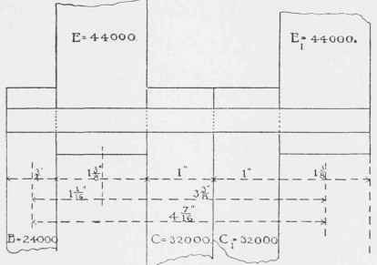
Fig. 168.
For practice, however, we will Figure out the bending-moments; they are : at E.
(left side) mE = 24000. 1 1/16 - 63555.0
= 25500 pounds-inch. Check (use right Bide) mE, = 32000. 2 3/16 + 32000. 1 3/16 - 24445.3 3/8
= 25500
At C we should have :
(Leftside)mc= 63555. l 3/16- 24000. 2 1/4
= 21472 Check (use right side) mc = 24445. 2 3/16 - 32000. 1
= 21472 At C, we should have : (left side) mCl = 63555. 2 3/16 - 24000. 3 1/4 - 32000.1
= 29027 Check (use right side) mC1= 24445. 13/16 - 32000. 0
= 29027
Had we used rule given on p. 51, Vol. I, we should have known that the greatest bending-moment was at C,. In applying the rule to this case the end load B should be deducted from the nearer reaction to B.
We might next try dividing the force B in two halves of 12000 pounds each, (heads 3/8" thick), leaving one at B and placing the other to the right of E1 This will restore equality to the forces E and E1, but it will be found that even this arrangement will not do, as the bending-moment at C or C1 will still be found to be too large, namely, = 27500 pounds-inch.
After these numerous failures it is evident that we cannot well arrange the heads satisfactorily along the pin, unless we enlarge the pin, or else divide up the larger forces which cause us most trouble. We decide to do the latter and divide A E into four parts of 22000 pounds each, with heads each 2,67/4 = 11/16" thick.
We now arrange the heads as shown in Figure 189. The correct way to calculate the bending-moment would, of course, be to consider the pin as a continuous girder running over four support-. This would make is, and E11 much larger than E and E111. Their heads would therefore have to be thickened so as not to crush the pin, or be crushed by it. It can readily be seen that were we to do this, the calculation would be almost interminable. Besides, practically, it would be expensive to use so many different sizes of rods, heads, etc. We must, therefore, assume that all the forces E, E1, E11 and E111 are equal. This they will be, too, for as soon as E1 and E11 tend to take more load, they will stretch under the added tension, and this stretching will bring the pin to bear more heavily on the ends and thus the strains will even themselves up.
Continue to:
My Books

