High-Tension Magnetos Of Independent And Dual Types. Part 8
Description
This section is from the "Motor Truck Design And Construction" book, by C. T. Schaefer. Also see Amazon: Motor Truck Design And Construction.
High-Tension Magnetos Of Independent And Dual Types. Part 8
Inductor Magnetos
The magnetos described previously, generating either high or low-tension current, were built on the principle of placing the winding or windings on the armature core, so as to rotate in unison with the armature.
The inductor type of magneto differs from the above, in that the windings are stationary within the magnetic field of the magneto and the armature is replaced by inductors which revolve, being attached to a shaft. In fact, these are the distinguishing features of this type of magneto. In other words, a stationary winding is used and mechanical energy is transformed into electrical energy through a distinctive principle known as induction.
This inductor type, like the primary and compound armature types, consists of permanent inverted U-magnets and pole pieces which form the magnetic field, mounted upon a non-metallic base. The winding or windings may be arranged for either a high or low-tension current and may either be placed in the magnetic field or at the rear end of the magneto.
The armature is replaced by inductors, mounted upon a shaft, this unit being termed the rotor shaft. The inductors are in some eases fan-shaped. The Remy inductor shaft, which is of this type, is illustrated in Fig. 57. It is made of laminated steel, claim being made for a better magnetic circuit with this construction. Each lamination is given an insulated coating on one side, the object of this being to eliminate eddy currents and to reduce heat losses.
The circuit breaker', or interrupter, is also used to open and close the primary circuit at the proper time, while the distributor is also resorted to to distribute the high-tension current to the proper cylinders. In fact, this type of magneto incorporates all the principal parts mentioned in connection with the previous types, such as the condenser, safety spark gap and switch.
The functions performed by these units are identical with those described previously. As mentioned above, the principal difference of this instrument over the others, lies in the method of generating the current.
Previously the method of magnetizing a bar was described in connection with the induction coil, and we may now investigate the method of utilizing this magnetism to produce electrical currents.
In a coil, an electrical current will be said to be flowing in the coil, meaning that it passes in the wire. Magnetic flux, however, will be said to pass through the core in either direction, the core serving as a path to direct the magnetism-through the coil. An electrical action is produced by the action of the magnetism in the core only when the strength of the magnetism varies, that is, when it increases or decreases. When this is the case an electromotive force is induced in the winding and. the more rapid the variation of the magnetism, the greater the induced electromotive force. Even if the core is traversed by a large amount of magnetism, it has no effect on the winding, as long as its value is unchanged. Electromotive force tends to produce an electric current and if the circuit is closed it actually does produce a current. The electromotive force produced in a single turn of winding is proportional to the rate at which the magnetism through that turn varies. A winding of several turns may be regarded as several windings of one turn, connected in series, so that to obtain a high induced electromotive force, a winding of several turns is used, just as several dry cells are connected in series to obtain a higher electromotive force from that obtained from a single cell.
In Fig. 58 are shown various positions of the inductors and their shaft. The upper view depicts the magneto with end plates removed, and the lower view represents a section of the upper view.
The stationary winding is securely held in place by the pressure of the pole pieces against it and by brass strips which have been omitted to simplify the illustration. The rear inductor, which is located to the rear of the winding, is indicated by dotted lines in the upper views. The inductors and core are secured to the shaft and rotate with it. constituting the only moving parts shown.
In order to form a path for the magnetic flux it is merely necessary to have a mass of iron joining the pole pieces, this being provided by the inductors, core and their shaft. The arrows show the path of the magnetism through the revolving parts.
In the position A, the front inductor is adjacent to the pole piece N, the rear inductor is adjacent to the pole piece , and the path is formed by the inductor shaft. When the cross-section of the inductor shaft is not great enough to carry all the flux, a core must be added to carry part of it. The magnetism, therefore, in position A, passes from the pole piece N, to the front inductor, through the core and shaft to the rear inductor, thence to the pole piece S. The magnetism through the winding is from the front to the back.
At B, the inductors are so located that each forms a path between pole pieces N and S, and the magnetism passes between the pole pieces without any of it passing through the winding.
At C, the conditions are similar to those at A, but the front inductor is adjacent to the pole piece S and the rear one adjacent to the pole piece A, causing the magnetism to pass through the winding from back to front, which is opposite to the direction which it had in position A.
Position D is similar to B, except that the front inductor is downward and the rear inductor upward. In this position no magnetism passes through the winding. From the above it can be seen that the magnetism passing through the winding is con-tinually varying, thereby inducing in the winding an electro-motive force.
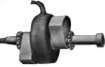
Fig. 57. Remy Induction Shaft.
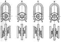
Fig. 58. Positions of Inductors and their Shaft.
Continue to:
My Books

