Two And Pour-Cycle Multi-Cylinder Motors. Part 11
Description
This section is from the "Motor Truck Design And Construction" book, by C. T. Schaefer. Also see Amazon: Motor Truck Design And Construction.
Two And Pour-Cycle Multi-Cylinder Motors. Part 11
The disadvantages of this system are apparent. The oil level varied constantly and so did the rate of supply to the bearing surfaces. When the crank case was replenished, the oil level was raised considerably and the supply to cylinder walls was generally excessive and the motor, in consequence, would pour dense smoke out through the muffler. In order to overcome this feature, some makers placed baffle plates between the cylinder and the crank case with an opening in the form of a rectangular slot for the connecting rod to pass through. Moreover this system required frequent attention from the operator, and if the latter were careless, the motor could easily be injured through the lack of oil.
Through the deficiencies mentioned above, lubrication by multiple feed mechanical oilers came into vogue. These oilers consisted of an oil reservoir carrying a series of plunger pumps, which forced the oil through individual lends to each part requiring lubrication. Each lead had its own pump, so that the oil was forced to each bearing in proportion to the speed of the motor. While this system was effective, its complications were objectionable. It was difficult to obtain a positive drive and the maze of oil tubes running from the oiler to the engine, rendered access to the latter difficult and presented a frail and non-mechanical appearance. It was also difficult to prevent leaks at the various connections and considerable oil was wasted.
Following this the pump circulating systems were introduced, as it was felt that a simpler system was needed and one that was at the same time thoroughly automatic. The gear and plunger types of oil pumps are most popular; however in some cases vane pumps are also used.
The gear pump consists of a casing in which fit snugly two spur gears, one driven by means of its shaft and gears from the cam shaft and the other by meshing with the former. The oil enters the housing on the side on which the meshing teeth separate and fills the spaces between adjacent teeth and the wall of the housing. It is thus carried around to the opposite side of the housing and leaves through an opening there.
Plunger pumps are generally placed inside the crank case and driven by eccentrics from the cam shaft. They consist of a brass barrel set in the case and carrying a plunger, which is held in contact with the eccentric by a spring, Below the spring a ball valve is placed. As the plunger moves upward, the lower end of the barrel increases in volume and oil enters through the ball valve. When the plunger is next moved down by the eccentric, the ball valve closes and oil is forced up through and out another ball valve, which remains closed on the upward stroke of the plunger.
In what follows the writer will attempt to describe and illustrate the most popular systems in use at present, among which both the gear and plunger types of pumps will be found.
Fig. 23 shows a mechanical oiler which operates in the following manner. A series of double plunger valveless pumps are driven by belt from a cross shaft which is driven by the engine. One set of plunger pumps lift oil from the reservoir and discharge it from the nozzles in the sight feed compartment, the amount of oil discharged being regulated by the adjusting screws A, directly in front of the sight feed. The other set of plungers take oil from the sight feed compartments and deliver it to the various parts of the engine through the oil lead connected with the pump outlet B. The plungers work alternately and each acts on a check valve for the other.
Fig. 24 illustrates a circulating splash system which has been used for a number of years on a prominent motor. Two plunger pumps are located in the lower half of the case and driven by eccentric from the cam shaft. One pump supplies oil to the timing gear compartment, and from these points it overflows to the splash troughs cast integral with the case.
The connecting rods are provided with dippers which are hollow and permit a certain amount of oil to reach the connecting rod bearings during each revolution of the crank pin. They also splash oil over the interior parts of the motor, the crank and cam shaft bearing housings being provided with pockets which store the oil and feed it to the bearings as it is needed.
Each connecting rod has a separate trough into which it dips, and the two forward ones are separated from the rear by a high partition, so that a positive oil level can be maintained for all conditions, when traveling up or down grade.
Fig. 25 shows another constant level splash system of the recirculating type. The operation of the system is similar to the one explained above, oil being supplied to the stationary troughs by a gear pump. Scoops on the connecting rods dip into these troughs and cause the oil to splash onto the pistons and into the small reservoirs which lead to the various bearings. The surplus oil drains back to the main reservoir, when it is thoroughly strained and again recirculated.
Fig. 26 illustrates a gravity-feed system using a gear pump for supplying oil to the gravity tank from the reservoir in the lower half of the case. This gravity tank is placed at the top level of the cylinders and has an oil lead of large diameter to each of the main bearings and the timing-gear compartment. The delivery pipe and leads are provided with strainers, so that the oil is thoroughly strained before being recirculated. The crank shaft journals and short arms are drilled through, so that the oil can pass from the main bearings to the connecting rods, centrifugal force being relied on to carry this oil to the connecting rods. Part of this oil works through these bearings and creates a spray, as in the force-feed system. This spray lubricates all other moving parts. It will be noted that the shape of the oil tank is such that when the car is moving up or down grade all bearings will receive an equal amount of oil. An oil gage on the dash shows the amount of oil in the tank, indicating that the pump is doing its work.
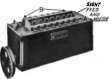
Fig. 23. Exterior of a Mechanical Oiler.
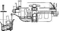
Fig. 24. Recirculating Splash System of Lubrication.
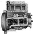
Fig. 25. Base Removed on Constant-Level Splash Lubricated Motor.
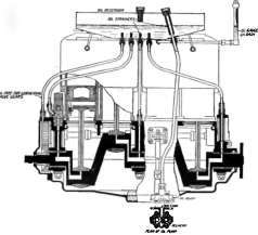
Fig. 26. Combination Pump and Gravity System.
Continue to:
My Books

