Inserted-Blade Taps
Description
This section is from the book "Modern Shop Practice", by Howard Monroe Raymond. Also available from Amazon: Modern Shop Practice.
Inserted-Blade Taps
The first cost of an inserted-blade tap may not be much less than that of a solid tap of the same size, yet the comparative cheapness of new blades, which can be inserted in the same body or holder when the first set becomes worn, makes this form very valuable for taps larger than 1 1/2 inches in diameter. The tap shown in Fig. 114 may also be used as an adjustable tap. The shank or holder A is made of machine steel, and the adjusting collars C, are beveled on the inside at one end, at an angle corresponding to the angle on the ends of the blades. An angle of 45 degrees will be found satisfactory.
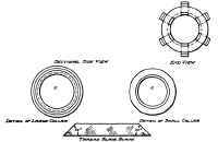
Fig. 114. Details of Inserted Blade Tap.
After turning the body or holder to size, and cutting the threads to receive the nuts, the slots for the blades may be milled. These should be cut deeper at the cutting end, in order that any change in the location of the blades may alter the size of the tap. A taper of 1/16 inch in 3 inches is ample. If the slots are milled on the universal milling machine, and the tap held in the universal centers, Fig. 115, the spiral head may be depressed sufficiently to give the desired angle. Sometimes a pair of centers mounted on special ways is used and is held in the milling-machine vise at the desired angle. The milling cutter should be set about 1/32 inch ahead of the center, in order that the face of the blade may be milled enough to take any inequality in the teeth at the cutting face. This is occasioned by the thread tool striking the face when it starts to cut. The amount milled should be just enough to leave the cutting face radial. The blades should be of an exact length and fit accurately in the slots. A gage of the form shown in Fig. 116 will insure uniform length. After the blades have been carefully fitted to the slots and to the gage, they should be inserted in the holder and secured by the nuts, as shown in Fig. 114. The outside diameter is then turned about .005 inch smaller than the size the tap is to cut, and the threads very carefully cut; after this the faces of the blades should be milled, as explained, the cutting end chamfered, and the necessary amount of clearance given the cutting edges by filing. The blades are now ready for hardening.
Fig. 115. Pair of Contora for Milling Taps Courtesy of Brown and Sharps Manufacturing Company, Providence, Rhode Island.
Fig. 116. Tap Gage.
During this process the blades should be subjected to a slow heat in a muffle furnace or a tube. When the blades reach a low uniform red heat, they should be immersed in a bath of lukewarm water or brine, and worked up and down to insure uniform results. After hardening, they may be brightened and drawn to a deep straw color.
For this operation it is well to place all the blades in a pan having a long handle, as shown in Fig. 117. Coarse sand to a depth of about 1 1/2 inches may be placed in the bottom of the pan with the blades. The pan should be placed over a bright fire, and shaken carefully, so that the teeth will not be dulled by striking the other hardened blades. The motion causes the pan to heat uniformly, and the sand keeps the surface of the work bright so that the temper colors may be readily seen. This method of drawing temper will be found very satisfactory on many classes of work. It is also used extensively where a great many pieces are to be colored uniformly by heat.
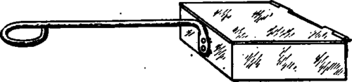
Fig. 117. Tempering Pan for Taps.
Continue to:
My Books

