Moulding Square Columns
Description
This section is from the book "Modern Shop Practice", by Howard Monroe Raymond. Also available from Amazon: Modern Shop Practice.
Moulding Square Columns
Square columns used in structural work are now common products of most foundries. They are invariably hollow. The exterior is usually plain though sometimes ornamented with simple devices, such as panels. The cores may be a combination of dry and green sand or dry sand alone according to the character of the work. They arc of the combination type when there are holes through the side, where the green saud may be supported. They are of thy sand when the sides of the casting are solid and the core can be supported at the ends only. The first type of column is shown in Fig. 65, and the second in Fig. 64. Where there are holes as shown in Fig. 65, the core is rammed in position. The pattern may consist of a hollow square box of any convenient length, provided only that it is longer than the column to be made. The flanges may be fastened to the pattern at the points which limit the length of the casting. These flanges should be thick enough to provide both for the thickness of the metal in the casting and the core prints. First ram and level the bed on which to lay the pattern. Then put on the drag, which is formed of loose sides and ends, held by cross bars. It must be long enough to hold the casting, but may permit the pattern to project through the ends. Ram the sides between the pattern and drag. Then set on the cope and ram that. For convenience of adjustment the cope had best be hinged to the drag. Turn back the cope and draw the pattern. Now place "false" side pieces in the mould. These are merely boards with drawing strips let into them and reaching to the top of the core. Their thickness is equal to that of the casting. Now place the false core bottom in the mould. This consists of a set of rectangular dry sand cores with projections on the under sides corresponding to the holes a a in the side of the casting. Next set the core bar in position. This is best made of a light I beam with boles drilled through the web. It should occupy the position in the mould as shown in Fig. 66. The I beam extends beyond the limits of the cope and is held down by driving wedges between the top flange and the end bars of the cope. Before this is done the core is rammed with green sand. The vent wires a a a a are laid in. If the core is much wider than the flanges of the I beams, bars b b are put through the holes in the web to hold down the sand. When the core has been rammed it is swept and sleeked down flush with the top of the false side pieces which rise to the points c e as indicated by the dotted lines.

Fig. 64.
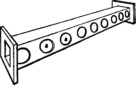
Fig. 65.
When this is done the false side pieces are withdrawn, the cope lowered to positioii and the 1 beam wedged down as directed. The metal, when poured, meets a core of dry sand d at the. bottom of the mould with green sand above.
When the four sides of the casting are to be solid as shown in Fig. 64 dry sand or loam cores are ordinarily used. These arc made over hollow iron cores which arc coated with dry sand or loam. The iron cores are perforated with a large number of holes, which permit the gases formed to escape through the interior.
Continue to:
My Books

