Example 4. Roll Follower With Path Not Intersecting Cam Center
Description
This section is from the book "Modern Shop Practice", by Howard Monroe Raymond. Also available from Amazon: Modern Shop Practice.
Example 4. Roll Follower With Path Not Intersecting Cam Center
1. Follower Positions
The follower positions in Fig. 82 are chosen precisely as in Fig. 81, and the subdivisions of the path of the follower similarly made. This case corresponds with that of Fig. 80, the line of travel not intersecting the center of the cam. The shape of the follower, however, is a roll similar to that just discussed in Fig. 81.
2. Cam Radii
The original radius CO is drawn as before. Then the radius CX, limiting the arc of rise, the radius CB, limiting the arcs of rest and fall, and the subdivisions of the arcs of rise and fall, are made exactly as in Fig. 81.
3. Follower Rotation
The treatment of follower rotation is the same as that in Fig. 80. The intersections R1, R2, R3 etc., being found, the distances R1L1,R2L2, R3L3, which the follower gets ahead of the radii, are set off exactly as in Fig. 80. In this case, however, the points L1 L2 and L3 are the centers of the rotated follower roll; and from these centers are struck the arcs representing the follower roll in its several rotated positions.
4. Tangent Line
A smooth tangent line is now drawn to the several positions of the rotated follower, thus giving the outline of the cap. In this case the outline of the cam giving the period of rest lies between the radii CN6 and CL6. In order that the full period of rest may be accomplished, it is necessary that the portion of the cam between these two radii be a true arc, struck from center C. Special attention should be given this point.
5. Testing
The cam should be tested by the tracing-cloth method, as before.
6. Pressure Line
The pressure lines are drawn as in Fig. 81 by joining the center of the follower roll in its rotated positions to the point of contact between the cam and the roll.
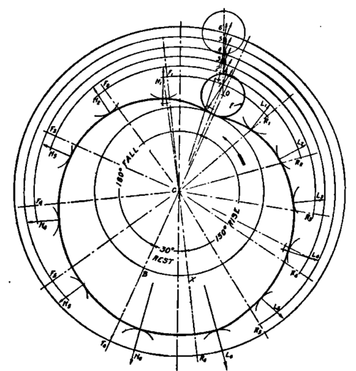
Fig. 82. Diagram of Cam with Roll Follower off Center.
Arrows, as before, indicate the direction of the pressure. These pressure lines may be rotated until they are collected along the line of travel, indicating the change in direction of the pressure between the cam and the roll as the roll passes over its path. A convenient method of laying off these pressure lines is to join the center of the cam C with the center of each roll; measure the angle which the line of pressure makes with this radius; and then transfer the angle to the proper point on the line of travel. This method is clearly indicated in the figure.
As before, it will be seen that the line of pressure lies quite close to the line of travel, and therefore the cam will be an easy working cam.
Continue to:
My Books

