Representation Of Objects
Description
This section is from the book "Modern Shop Practice", by Howard Monroe Raymond. Also available from Amazon: Modern Shop Practice.
Representation Of Objects
Rectangular Prism Or Block
In Fig. 122 there is represented a rectangular prism or block, whose length is twice its width. The elevation shows its height. As the block is placed at an angle, three of the vertical edges will be visible, and the fourth, invisible. In mechanical drawing, the edges, which in projection form a part of the outline or contour of the figure, must always be visible, hence are always drawn as full lines, while the lines or edges which are invisible are drawn dotted. The plan shows what lines are visible in elevation, and the elevation determines what are visible in plan. In Fig. 122, the plan shows that the dotted edge AB is the back edge, and in Fig. 123, the elevation shows that the dotted edge CD is the lower edge of the triangular prism. In general, if in elevation an edge projected within the figure is a back edge, it must be dotted, and in plan, if an edge projected within the outline is a lower edge, it is dotted.
Triangular Prism Or Block
The end view shown in Fig. 123 is obtained by projecting the points of the plan across to a plane at right angles to the horizontal and vertical planes, then revolving them down through 90 degrees and continuing the projections to meet the projection lines drawn across from the elevation. Connecting the points thus obtained gives the end view. End or side views of any object are obtained by projection in this way.
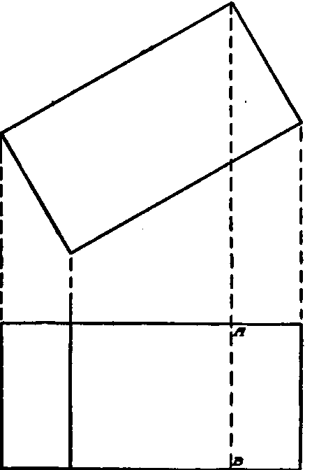
Fig. 122. Projections of a Rectangular Priam or Block.
Triangular Block With Square Hole
The plan, elevation, and end views of a triangular block with a square hole from end to end are shown in Fig. 124. In this case the plan and elevation alone would not be sufficient to positively determine the shape of the hole, but the end view shows at a glance that it is square.
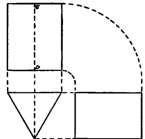
Fig. 123. Projections of a Triangular Prism or Block.
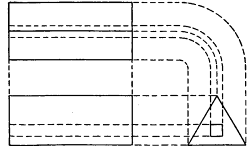
Fig. 124. Projections of a Triangular Block with Square Hole.
Continue to:
My Books

