Construction Of A Goods Lift
Description
This section is from the book "Cassell's Cyclopaedia Of Mechanics", by Paul N. Hasluck. Also available from Amazon: Cassell's Cyclopaedia Of Mechanics.
Construction Of A Goods Lift
The accompanying illustrations are intended to explain the construction of a goods lift, to be worked by hand, and fitted with balance weights. The extreme dimensions of the lift are 4 ft. wide, 3 ft. deep, 6 ft. 6 in. high: this is the largest size usually made to work by hand, and it is capable of carrying safely 10 cwt. If the lift is to be used by passengers, safety catches and another guide should be added. The construction is simple, and consists of a skeleton frame of 2-in. by 2-in. stuff, filled in with panels of 5/8-in. niatchlining. The top and under frames are dovetailed together at the corners as shown in Fig. 5, the pins being on the front and back rails in order to prevent the cage spreading in this direction; the guides prevent the cage opening in the other direction. The corner studs are stub-tenoned and table-haunched into the frames, and kept in position by four 5/8-in. wrought-iron bolts E running from top to bottom of the cage. The matchlining is fitted into 3/8-in. grooves in the frame, on three sides and the top; the floor is formed of 1-in. boards, nailed on the under frame, and running in a direction transverse to the top; a rail 4 1/2 in. by lin. runs across the back to strengthen the match-lining. The cage is hung to a wrought-iron rail tin. by 3 in., spread at the ends, and drilled to receive a bolt that runs through to the bottom, where it beds on an iron plate C (Figs. 2 and 4). The end of this rail may be forked over the guide post G, Fig. 1, to form a runner. F P are the balance frame guides. E is the frame, which is filled in with cast-iron weights. H,H are pieces of l 1/4-in. by 3/4-in. oak, fixed to the side of the cage to form runners; or, if preferred, iron bracket pieces, as at K, may be used. T T show the trimmer joists around the openings. These cages are usually made of good sound yellow deal, painted or stained, and varnished; but for a goods lift that is in constant use, it is advisable to make the frame and guides of oak or teak. Fig. 1 shows a half vertical section and half front elevation; Fig. 2, a half plan and half horizontal section; Fig. 3, an enlarged section through the top corner of frame; Fig. 1, an enlarged section through the bottom corner of the frame. Fig. 5 shows the joints at the corner of the frame, and Fig. 6 the method of tenoning the posts.
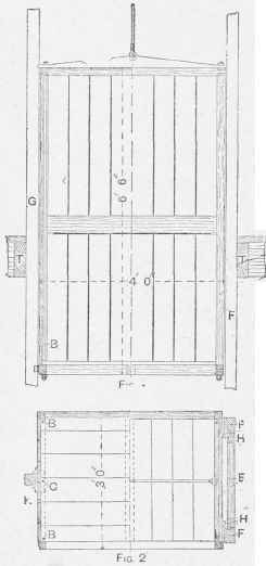
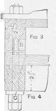
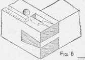

Fig. 6. Construction of a Goods Lift.
Continue to:
My Books

