How To Make A Studio Camera
Description
This section is from the book "Cassell's Cyclopaedia Of Mechanics", by Paul N. Hasluck. Also available from Amazon: Cassell's Cyclopaedia Of Mechanics.
How To Make A Studio Camera
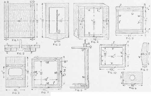
A studio camera to take 12-in. by 10-in. plates may be made of 3/8-in. mahogany. First construct the baseboard (Fig. 1) of the size shown in the illustration, by tongueingtogether. Then make two scrips E and P (Fig. 2) 16in. by 3/4 in. by 3/16; in., and glue and screw these in the spaces A and B (Fig. 1). They will then be iin. apart, and extend 2in. from the edges, and stand rffin. A strip I 2 1/4-in. by 16in. is next strongly attached, as in Fig. 2, with a?-in. slot for a clamping rod runiling from about 2 in. or 3 in. from each end. A similar slotted rail is then made to come over C and D (Fig. 1). Next form the extension frame (Fig. 3) to run freely in the grooves of the baseboard rails. Fit the focussing screw J (which may be purchased ready prepared for about 4s) by screwing down the bolt G to the baseboard, and the nut to the end of the extension frame at H. Construct the sliding frame (Fig. 4) by dovetailing four pieces each 16in. by 3 in. Inside this fit a frame K 1 3/8 in. wide, flush with the front edges, and screw across two grooved pieces L for the rising front, 3in. by 16in. The rising front board may next be got out, with the two rebated rails for the sliding front; this is sufficiently explained by Fig. 5. The sliding front or lens board is shown in Fig. 6. Now make the back frame (Fig. 7), giving about 3/8in. slope to the top and bottom to allow of swing. These four pieces, 14 3/4in. by 3 in., are dovetailed together. Then sink the nuts for the thumbscrews B2 and the pivots A2. Inside the framework fit carefully a framework M exactly 3/8in. from the back edge, and lin. wide; cover it with velvet on the near side. It is an advantage to bevel the frame towards the centre to allow of central expansion of bellows when closed. Proceed to fit the clamping rods N (Fig.8). These consist of alongscrew and nut, but the thread O need only extend about 1 in. P is a circular place to grip the side rail, Q a washer, and E the thumbscrew or clamping nut. The bellows may be obtained ready made from dealers in photographic materials. Glue the front of the bellows to the framework L (Fig. 4) and the back to the frame M (Fig. 7), and place under underpressure till thoroughly dry. The fixed frame (Fig. 11, side view) is prepared 16in. by 31 in. The back frame is fitted with the pivots to the fixed frame at V, and the whole is then made up and screwed firmly to the back of the extension frame. Now make the r-eversing back (Fig. 9) by first joining up a frame of four pieces, and across them glue and screw two strips S and T l 1/8 in. by 14 in., with Jin. groove at U. A further strip may be fitted across between the two at W (not shown) to form a stop for the slide. This must all be done in 3/6in. stuff to make the frame exactly | in. thick when finished.
The focussing screen frame is formed as in Fig. 10. The tongue X engages with the groove D (Fig. 9),and the 1/16in. rebate v is for the focussing ground glass which is held in by narrow strips of brass across the corners. Attach the screen frame to the reversing back by double hinges at ZZ (Figs. 9 and 10).
How To Make a Studio Camera.
Continue to:
My Books

