Hydraulic Engines
Description
This section is from the book "The Engineer's And Mechanic's Encyclopaedia", by Luke Hebert. Also available from Amazon: Engineer's And Mechanic's Encyclopaedia.
Hydraulic Engines
Hydraulic Engines, are all kinds of machines which either receive motion from the weight or impulse of water, or are employed in raising it; but the term is sometimes used to denote a machine which in its general construction resembles a steam engine, but the piston of which is impelled by the pressure of a column or head of water. The annexed figure is a representation of a statical hydraulic engine erected by Mr. Man waring, at Messrs. Cook &
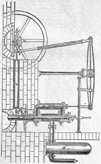
Co.'s Alum Works, near Whitby. A is the pipe by which the supply of water is brought from a head 170 feet above the engine; B is a vessel containing air, the continual elastic pressure of which prevents the blow that would otherwise be occasioned by the descent of the water; c is a throttle valve; d d is a hollow open cylinder, working within an exterior one, and closely applied to that cylinder, at the parts e e e e, but elsewhere leaving a vacant space between the two cylinders for the reception of the water h h are packings, in order to prevent the escape of the water between the two cylinders; and i i are adjusting screws, to tighten the packing in proportion as it is worn away; f f are two passages that lead into the upper and lower ends of the pipe g, in which the piston w works. When the cylinder d d is in the position represented in the cut, the communication is open by means of the upper pipe f, for the water to flow into the pipe g above the piston w; at the same time the passage is open for the water in the cylinder g, below the piston, to flow out through the lower pipe f and through the lower part of the open cylinder d, into the pipe x, which is somewhat more than 30 feet long, and terminates in a cistern of water.
There is therefore, above the piston to, a hydrostatic pressure equal to 170 feet of water, and below it a partial vacuum; the piston consequently descends to the bottom of the pipe g. By the time that it has arrived in this position the cylinder d will also have descended so far as to have opened the communication between the entering water and the lower pipe f, and to have shut off its communication with the upper pipe f; the hydrostatic pressure is therefore transferred to the under part of the piston, which consequently rises, while the water above the piston pours into the top of the cylinder d, and escapes through the pipe x. The alternate motion of the slide or cylinder d is thus effected. The rod of the piston p p is attached at its top to one end of the beam; at the other end of the beam is a rod, terminating below in the crank m; the oscillating motion of this crank is transferred, by means of the connecting bar f, to the axis k, on which is placed the curved tooth or cam n; the latter is enclosed within the rectangular frame (or cam box) j, and, being movable in a horizontal position, is consequently made to perform a backward and forward motion, by the cam passing first on one and then on the other side of the box.
To the outside of the box are fixed two guide bars, supported on thin bearings o o, the connecting rod p at one end to the guide bar, and at the other end to the arm q of a bent lever, having for its fulcrum the pivot r; the other end of the lever is forked, and embraces the pipe x; one of these forks s is connected with the lower end of the upright rod t, and the other fork is connected with a similar rod. These rods are fastened at top to the two ends of a cross bar, to the middle of which is fixed the rod u, which works in the stuffing box v, and gives motion to the slide d. The slide remains stationary nearly half a stroke of the piston, in order to allow the water to act with its full force; and this is effected by its being necessary for the cam, after it has moved the box in one direction, to perform about a quarter of a revolution before it can act on the opposite side of the box. The reason for making the passages f f as large as represented, is to diminish as much as possible the friction of the water, which otherwise would retard the motion of the piston. Engines upon the principle of the above have been long known, and some were erected in Cornwall more than sixty years ago.
Some of the earlier attempts to construct hydraulic engines upon the principle of the steam engine failed, because water, not being elastic, could not be made to carry the piston onwards a little, so as to close one set of valves, and open the other. In an engine erected by Mr. Trevethick, about thirty years ago, a tumbler connected with the valve gear performs the office instead of the expansive force of the steam at the end of the stroke. This is now, however, much better effected by the introduction of an air vessel similar to that shown in Mr. Manwaring's engine, which has besides, the effect of preventing a concussion at the end of each stroke.
Mr. Seidler has taken out a patent for an engine, which he calls a hydraulic engine, but which we think should rather be styled a pneumatic engine, as raising water is merely one of the objects to which he proposes to apply the principle, which is that of employing compressed air as a medium for transmitting the power of any prime mover to machinery at a distance, or in situations where the ordinary modes of connexion would be inconvenient or impracticable. The principle itself is very old, having been employed by Papin as noticed under the word Air. The engraving on the next page represents the application of the principle to the purpose of raising water from any depth, and through straight or circuitous passages, a a represents a cylinder, in which a piston, p, works by means of a steam engine or other power, h a are copper pipes, forming a communication between the cylinder a a and the cast iron tank or vessel it; o o is a large delivery pipe, of copper or other material, through which the water is conveyed from the tank, and discharged; at r is an air-tight partition, dividing the tank into two parts, k and l; and s s are two air-tight partitions, proceeding from the top nearly to the bottom of the tank; e is a two-way cock, for effecting an alternate communication between a and k, and between a and f.
The other parts of the machine will be explained in the following description of its action. Suppose the piston p to be raised from its present position in the cylinder, the air above it will be conveyed through the valve c, and the pipe h into the vessel k, and force the water contained therein through the valve t, up the pipe o o, while air will be supplied to the cylinder below the piston through the valve b. When the piston descends, the air will pass from the lower to the upper side of it by the valve d; this operation is to be continued till all the water is forced out of k, when the two-way cock e must be turned to change the communication through the valve c to the pipes rf, and the part of the tank f at the Same time; the air which was forced into k will be permitted to re-enter the cylinder through the pipe w, as shown by the dotted lines in the cock e, so that no air will be required to enter at the valve 6 except at the commencement of the operation, or when any of the air is discharged with the water, or otherwise dissipated. When the air is liberated from the receptacle k of the tank, it will be again filled with water through the valve m, the valve i being shut by the pressure of the water in the pipe o o.
During this time, the water in l will be forced through the valve u; in the same manner from k, through the valve i. The cock e to be turned by the hand or by the machinery, after such a number of strokes of the piston in the cylinder as is sufficient to displace the water in one division of the tank. For machines for raising water, see Pumps and Water Works.
Continue to:
My Books

