Window. Part 3
Description
This section is from the book "The Engineer's And Mechanic's Encyclopaedia", by Luke Hebert. Also available from Amazon: Engineer's And Mechanic's Encyclopaedia.
Window. Part 3
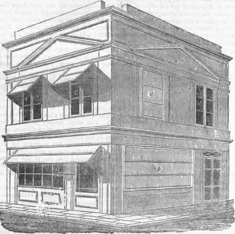
In the annexed engraving is represented a perspective view of the comer-house of a street, in which the metallic shutters and sun-blinds are exhibited as applied thereto. At a is a shop-window, and at 6 a shop-door, over which is projected two of the metallic shutters as a sun-blind, having also end blinds of silk cloth or other desirable substance, in the form of sectors of circles. In this case the third shutter, which forms the set, is drawn up and deposited behind the entablature. On the first floor above the shop, c c exhibits the application of the same thing on a small scale to private windows. At d is shown a window unclosed; that is, the shutters are supposed to be withdrawn entirely, and deposited immediately above or below it, as the patentees adapt them to both situations. At e is a window entirely closed by the shutters, presenting a barrier against bnrglars, said to be bullet-proof; and at o is shown one of the shop windows, similarly closed. The shutters are made in the following manner. Having determined the number of plates or pannels a shutter is to contain, (usually three or four,) the iron or steel plates are well hammered in the manner of saw plates, so as to condense the metal and flatten the surfaces.
The plates are then enclosed in grooves made in a rectangular frame of bar-iron, and strongly rivetted thereto. Thus framed, they are connected together at pleasure, by the lower horizontal bar of one, and the upper one of the next being cut into acute angles, that hook into one another; and they are thus drawn up or let down in succession, by sliding with their vertical sides in deep grooves cut in bars of wrought iron, which form the styles to the window. The upper portion of these grooved metallic styles is made to separate from the lower, by turning upon a pivot or hinge joint, at the top of the window, by which means the shutters, while contained in the grooves, may be projected out to an angle of about 60 degrees from the perpendicular, and form the sun-blinds. The patentees have designed several movements for raising or lowering the shutters; but we adopt that which is specified under the patent, with reference to the annexed sectional figure. From a and b to c and d, is one of the side styles to the window; from a to f is a continuation of the style and frame behind the entablature, where all the three shutters g, h and i, are drawn up and deposited, when the shutters are not in use.
The groove for the upper shutter g does not permit it to descend lower than b, nor does the groove for the middle shutter h permit that to descend further than c, but the groove for the lower shutter i is extended from the top fto the bottom d. The sun-blind is projected only when they are all down, by which means the two upper shutters are unlocked from the lower, and the latter is afterwards drawn up to the top, as shown in the figure. To the movable part of the style is fixed a curved rack k, the teeth of which geer into those of a pinion l; the axis of this pinion carries a winch m, by turning which, the sun-blind is thrown out, or drawn in. To steady the motion of the blind, the movement described is made to communicate with a similar rack and pinion on the opposite side of the window; for this purpose there is placed on the axis of the pinion l behind it, a small chain pulley, round which an endless pitched chain n passes, and also over a similar pulley o; the axis of the last mentioned is a long shaft, extending horizontally across the window (above the glass) to the opposite side, where a corresponding apparatus projects, and supports that side of the sash blind.
In order to fix the blind at any required angle that it may be desired to project it, there is on the axis of i, a ratchet-wheel, with a pall above p, which falls into the teeth on its periphery, and prevents its return without being lifted up.
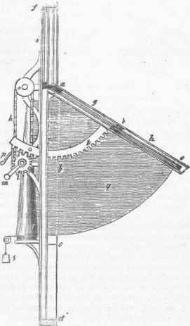
The side or end blinds, one of which is represented at g, are made of cloth, or other flexible substance; one side is attached to the projecting part of the style, and the other, passing through a long and very narrow slit, is attached to a conical roller r; when the shutters composing the blind are drawn in, the conical roller is turned by means of a descending weight s, which then winds upon it, in even layers, the sectorial blind. To the middle of the lower edge, and at the back of the bottom shutter i, a suitable line or chain is attached. This line is carried up vertically, then passes over a pulley at the top of the frame, and from thence over side pulleys down to a barrel on one side, on which the cord is wound. The lower ledge of the shutter i has likewise a projecting ledge; on the drawing up of the lower shutter, therefore, by the cord and winch described, the bottom edges of the middle and upper shutters come in contact with, and rest upon the ledge, and are thereby carried up altogether into the casing behind the entablature; to keep the shutters in the situation they are thus put, a pall drops into the teeth of another ratchet-wheel placed on the axis of the winding barrel.
Subsequent improvements have been effected upon the foregoing, which chiefly consist in substituting, for the movement we have described, long revolving screws extending from top to bottom on each side of the window. A simultaneous motion is effected in the screws, by means of a bar extending across the bottom of the window, and connecting, by bevil wheels, both screws with a winch handle by which they are turned. Upon the screws are fitted nuts, to which are attached the shutters; and, therefore, by the operation of turning the handle, the shutters are steadily raised or lowered into or out of their case.
Continue to:
My Books

