Mechanical Movements
Description
This section is from the book "Spons' Mechanics' Own Book: A Manual For Handicraftsmen And Amateurs", by Edward Spon. Also available from Amazon: Spons' Mechanics' Own Book.
Mechanical Movements
Those means by which motion is transmitted for mechanical purposes are known as mechanical movements. Motion, in mechanics, may be simple or compound. Simple motions are, - those of straight translation, which, if of indefinite duration, must he reciprocating; simple rotation, which may he either continuous or reciprocating, and when reciprocating is called oscillating; helical, which, if of indefinite duration, must he reciprocating. Compound motions consist of combinations of any of the simple motions. Perpetual motion is an. incessant motion conceived to be attainable by a machine supplying its own motive forces independently of any action from without, or which has within itself the means, when once set in motion, of continuing its motion perpetually, or until worn out, without any new application of external force; also the machine itself by means of which it is attempted, or supposed possible, to produce such motion; an invention much sought after, but physically impossible.
Fig. 737. In this the lower pulley is movable. One end of the rope being fixed, the other must move twice as fast as the weight, and a corresponding gain of power is consequently effected.
Fig. 738 is a simple pulley used for lifting weights. In this the power must be equal to the weight to obtain equilibrium.
Fig. 739. Blocks and tackle. The power obtained by this contrivance is calculated as follows: - Divide the weight by double the number of pulleys in the lower block; the quotient is the power required to balance the weight.
Fig. 740 represents what are known as White's pulleys, which can either be made with separate loose pulleys, or a series of grooves can be cut in a solid block, the diameters being made in proportion to the speed of the rope; that is, 1, 3, and 5 for one block, and 2, 4, and 6 for the other. Power as 1 to 7. Figs. 741, 743 are what are known as Spanish bartons. Fig. 742 is a combination of two fixed pulleys and one movable pulley. Figs. 744 to 747 are different arrangements of pulleys. The following rule applies to these pulleys: - In a system of pulleys where each pulley is embraced by a cord attached at one end to a fixed point, and at the other to the centre of the movable pulley, the effect of the whole will be the number 2, multiplied by itself as many times as there are movable pulleys in the system.
Fig. 748. Mangle-wheel and pinion - so called from their application to mangles - converts continuous rotary motion of pinion into reciprocating rotary motion of wheel. The shaft of pinion has a vibratory motion, and works in a straight slot cut in the upright stationary bar to allow the pinion to rise and fall, and work inside and outside of the gearing of the wheel. The slot cut in the face of the mangle-wheel and following its outline is to receive and guide the pinion-shaft, and keep the pinion in gear.
Fig. 749. Fusee-chain and spring-box, being the prime mover in some watches, particularly in those of English make. The fusee to the right is to compensate for the loss of force of the spring as it uncoils itself. The chain is on the small diameter of the fusee when the watch is wound up, as the spring has then the greatest force.
Fig. 750. A frictional clutch-box, thrown in and out of gear by levers at the bottom. This is used for connecting and disconnecting heavy machinery. The eye of the disc to the right has a slot which slides upon a long key or feather fixed on the shaft.
Fig. 751. Clutch-box. The pinion at the top gives a continuous rotary motion to the gear below, to which is attached half the clutch, and both turn loosely on the shaft. When it is desired to give motion to the shaft, the other part of the clutch, which slides upon a key or feather fixed in the shaft, is thrust into gear by the lever.
Fig. 752. Another kind of clutch-box. The disc-wheel to the right has 2 holes corresponding to the studs fixed in the other disc; and being pressed against it, the studs enter the holes, when the 2 discs rotate together.
Fig. 753. Used for throwing in and out of gear the speed motion on lathes. On depressing the lever, the shaft of the large wheel is drawn backward by reason of the slot in which it slides being cut eccentrically to the centre or fulcrum of the lever.
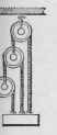
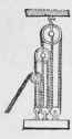
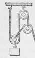
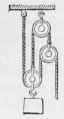
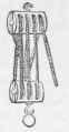
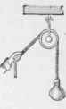
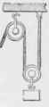
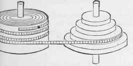
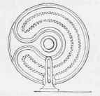
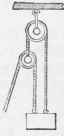
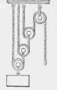
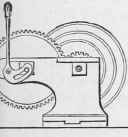
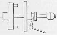
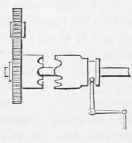
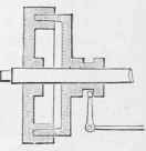
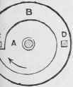
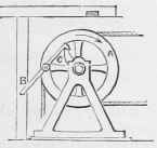
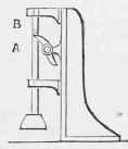
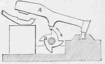
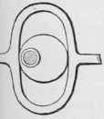
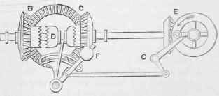
Fig. 754 is a tilt-hammer motion, the revolution of the cam or wiper-wheel B lifting the hammer A 4 times in each revolution.
Fig. 755. Intermittent alternating rectilinear motion is given to the rod A, by the continuous rotation of the shaft carrying the 2 cams or wipers, which act upon the projection B of the rod, and thereby lift it. The rod drops by its own weight. Used for ore-stampers or pulverizers, and for hammers.
Continue to:
My Books

