Problem 121. Pattern For An Octagon Spire Mitering Upon A Roof At The Junction Of The Ridge And Hips
Description
This section is from the book "The New Metal Worker Pattern Book", by George Watson Kittredge. Also available from Amazon: The new metal worker pattern book.
Problem 121. Pattern For An Octagon Spire Mitering Upon A Roof At The Junction Of The Ridge And Hips
In Fig. 446, let A B C represent the front elevation of the roof and A' a c C' the corresponding plan.
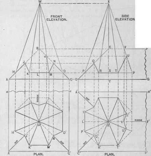
Fig. 446. - Plans and Elevations of Spire.
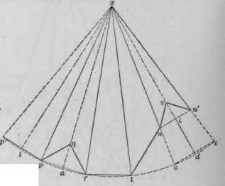
Fig. 448.-Pattern.
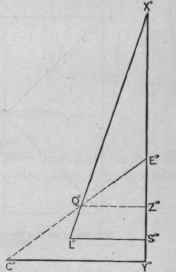
Fig. 447.-Seotion of Spire on Line of Hip.
Pattern for an Octagon Spire Mitering Upon a Roof at the Junction of the Ridge and Hips.
Also let D E F G be the side elevation of roof, and A" a' c C" the corresponding plan. In the front elevation let W O N M K J H represent the octagon spire and H' J' K' M' N' O' the corresponding plan.
In the side elevation the spire is represented by P X U T R Q, and in plan by P' Q' R' T' U' V. Only the points in plans are designated by letters which represent similar points in the elevation. In order to draw the plans and elevations, including the miter lines, it may be found convenient to first construct the entire octagons, as indicated in the plans, and from these to project the elevations above, as shown. From the point u in front elevation, which represents the intersection of one of the rear angles of the spire with the roof, carry a line parallel with B F, cutting X p. From the point U draw the miter line U T, and from the points V U drop perpendiculars to plan, cutting X' V' and X' U', from which points can be drawn the miter lines V' U' T' of the plan.
To obtain the miter line P' Q' R' of plan, from which is obtained the miter line Q R of side elevation, a diagram has been constructed in Fig. 447 which shows a section of spire and roof on the line C" X' of plan. To construct the diagram proceed as follows: Draw any line, as X° Y°. From X° set off the distance X E of side elevation or W B of front elevation. The point E° represents the junction of hip and ridge. From X° set off the distance X S, and erect the perpendicular S° L°, making it in length equal to S P, and connect L° X°. Then X° S° L° is a duplicate of X S P. From X° set off the distance X Y and erect the perpendicular Y° C°, in length equal to X' C" of plan, and connect C° E°. Then L° X° represents one side of spire, and C° E° the hip of the roof, and the point Q° the point of junction between the two.
As the spire is a perfect octagon, the profile of the side just constructed is in nowise different from either of those shown in the elevations. It simply has in addition the profile of one of the hips by means of which the correct hight of its intersection with the same (the point Q°) is determined. Draw Q° Z° parallel with C° Y°, and from the point X' of plan set off the distance Z° Qo of diagram, as shown by X' Q'. Connect R' Q' and Q' P'. From the point Q' in plan carry a line parallel with the center line X X', cutting the hip line D E at Q. Draw Q R, which shows the miter line in side elevation. From the point Q can be drawn the line Q J, cutting the hip lines A B and B C in front elevation at the points J and N, and the miter lines J K and M N drawn. The points K M in front elevation correspond with the points K' M' of plan.
For the pattern proceed as follows: Draw l x of Fig. 448, equal to P X of side elevation, and from l erect the perpendiculars l p and l p', equal in length to L' P' of plan or L M of front elevation. From p and p' draw lines to x, as shown. From x as center, with x p as radius, describe an arc, as shown by p' e, indefinite in length. Set the dividers to the distance p p and step off spaces from p, as p r, r t, etc., until as many sides are set off as are desired to be shown in one part of the pattern. For convenience in describing the pattern draw the lines x r, x t, x c. Connect c and e and make c d equal to p l and draw x d. Bisect p r and draw x a, and from x, on xa, set off the distance X° Q° of Fig. 447, locating the point q. Draw p q and q r. From x, on x d, set off the distances X V and X U of side elevation, locating the points v and i. Through i draw a perpendicular cutting x c and x e in the points u and u', then draw u' v v u and u t. Then x p'p q r t u v u' is the pattern for part of spire shown on plan by X' I P' Q' R' T' U' V' I',
Fig. 448 shows a little more than half the full pattern, which will be readily understood by a comparison of reference letters.
Continue to:
My Books

