Double-Rake Moulding Joint
Description
This section is from the book "Practical Sheet And Plate Metal Work", by Evan A. Atkins. Also available from Amazon: Practical Sheet And Plate Metal Work.
Double-Rake Moulding Joint
Where the gable-end of a building is not square to the sides, but is inclined, the problem of connecting the two mouldings with a single joint becomes more difficult than in the last case. It represents, perhaps, one of the most complicated cases of sheet-metal cornice jointing it is possible to have. However, if the reader carefully follows each step in the setting out as shown, he should, even without a very extended knowledge of geometry, be able to accomplish the task of striking out a pattern.
One example of this class of jointing is shown in Fig. 189, in which the gable-end of the building makes an angle of 120° with the sides, whilst the pitch of the roof is 30°.
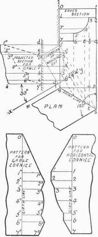
Fig. 189.
The shape of the section is first set out, and a plan drawn showing the required angle of 120°. From each numbered point on the section projectors are run down to the joint line, the line n p then being drawn square across.
The pattern for the cut on the horizontal cornice can now be set out. First, lay down the girth line, as shown, by making it equal in length to the sum of the numbered parts on the section. Then through each point draw lines square across, and cut these off equal to the lengths of the lines between n p and the joint line. Thus, 1 1 and 2 2 are each equal to p s, and 3 3 will be the same length as u t, the other lengths passing through 4, 5 and 6 being cut off in the same manner.
Before the pattern for the gable-cornice can be laid out, the length of its construction lines must be obtained, this being done by drawing a side elevation of the inclined cornice. Draw x y parallel to m n, and then from the latter line run up a prependicular from n to intersect x y in 7'. Now draw the line 7' k at the required angle of 30°. Through each point on the joint line run up projectors, and cut these off, above x y, to the heights of the corresponding lines drawn above 7 a up to the eaves section - that is, a' 1' = a 1; a' 2' = a 2, b' 3' = b 3, and so on for the rest of the lines. If the points as found are joined up, it will be seen that the figure (shown marked out by small dots) will be the elevation of the moulding-cut. From this, the projected section for the gable-cornice can be obtained. Draw the line 1" d perpendicular to k 7', and passing through 0'; then mark off d 1" and e 2" each equal to 0 1. Afterwards, f 3" should be made equal to l 3, the length g 4" the same as r 4, also h 5" and i 6" each equal to 7 6. Joining the points up, the figure (shown by long dots) will give the shape of cornice-section, for the gable, that will join on to the given eaves section.
For the pattern of the gable-cornice cut, the girth line will be measured from the projected section, and it will be seen that the same numbers are used in both section and pattern. The lengths of the construction lines on the pattern are cut off equal to those on the right hand of 7" d measured up to the points 1', 2', 3', etc. Thus, on the pattern, 1" 1° = d 1', 2" 2° = e 2', 3" 3° = f 3', and so on for the remaining lines.
In bending into shape, the gable-cornice pattern will, of course, be bent to the projected section, whilst the pattern for the horizontal moulding will be shaped to the eaves section.
Although the setting-out in the last three cases has special reference to sheet-metal roofing work, it should be borne in mind that the principles will apply to all kinds of work where moulding or beading has to be fixed in a similar manner.
Continue to:
My Books

