Roof Finial
Description
This section is from the book "Practical Sheet And Plate Metal Work", by Evan A. Atkins. Also available from Amazon: Practical Sheet And Plate Metal Work.
Roof Finial
There can, of course, be a multitude of designs for a sheet-metal finial, all depending upon the taste of the designer, the limit of cost, and the kind of building that the finial is to be fixed upon. For a high building it should be remembered that small details of ornament on the finial are a waste of time and money, as they are, of course, not noticed from the ground.
A very simple form of hexagonal finial is shown in Fig. 194. It can be made out of either copper, brass, zinc, or galvanised sheet iron, the latter two metals being the ones usually chosen.
The half-sectional elevation and the pattern for one of the strips are shown set out in Fig. 195, After having drawn in the shape of the section as seen, the curves that form the outline are divided up into a convenient number of parts; there being seventeen in the present case. Lines are then drawn at points a, b, c, and d, making angles of -
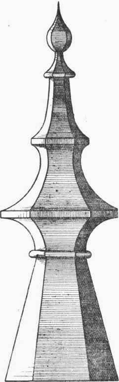
Fig. 194.
360 / twice number of sides = 360/ 12 = 30° with the cross lines; these really being plan views of one of the joint lines. Lines are then drawn down through each point parallel to the centre line on to one of the 30° lines.
For the strip pattern the girth line is first stretched out, its total length being made up by adding together the lengths of the different parts, as numbered on the outline in the sectional elevation. Lines are then drawn across the girth line through each numbered point, and the lengths of these cut off equal to the corresponding lines in the elevation between base and joint lines. Thus, for example, the lines 6 6', 8 8', and 9 9' on the pattern will be respectively equal to the lines 6' 6", 8 8', and 9' 9" on the elevation. In exactly the same way all the other lines required for marking the width of the pattern at the different parts can be measured from the elevation. It will be noticed that there are four 30° lines in the elevation, the object of the three top ones, of course, being to avoid having to run the dotted lines for the widths all the way down to the base line. Instead of having the whole strip in one piece, it can, if necessary, be divided up into any number of parts, depending upon the size of the finial. After the pieces are connected, the sections can then be jointed together.

Fig. 195.
Sometimes the base part of the finial is made separately, which, it can be seen in this case, will come out as a frustum of a hexagonal pyramid. The apex of a complete pyramid can be found by producing the line 17 to 16 (Fig. 195) up to meet the centre line at T. The setting out of this frustum is shown separately, and to a smaller scale, in Fig. 196. The point l is swung around d to l', and joined to the apex T. Then taking T as centre and T l' as radius, the arc is described as shown. The compasses are now set to twice the length l m, and the points L stepped around the arc. It is a good plan to mark off one side more than is required (in this case seven), and then bisect the two end parts to obtain the seam exactly up the middle of a side. These joint lines are marked T M in the figure. The line T t' will give the radius for cutting off the points to form the inside part of pattern shown by the lines t t.
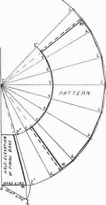
Fig. 196.
In making up the finial the strips should first be bent to the required shape of section - that is, the centre line of the strip should be formed to the outline in the elevation (Fig. 195). The strips are then all tacked together with solder, and after carefully testing the finial to see that it is symmetrical and without twist, the joints soldered up, as much of this being done from the inside as possible.
Continue to:
My Books

