Studies In Electricity. VI. Magnetic Field and Polarity
Description
This section is from the book "Amateur Work Magazine Vol1". Also available from Amazon: Amateur Work.
Studies In Electricity. VI. Magnetic Field and Polarity
The space all around a magnet over which the magnetic forces extend is termed the "field." These forces vary in strength, being strongest near the poles and growing weaker as the distance from the poles increases. The direction in which these forces act also varies with the different parts of a magnet, but this variation is along certain well-known and regular lines. This may be shown in a very interesting way by the following experiment: Over a bar-magnet place a sheet of smooth writing paper; on the paper, dust some fine iron filings. As they settle down they will form lines similar to those shown in Fig. 20. It may be necessary to gently tap the paper a few times to have the lines clearly shown.
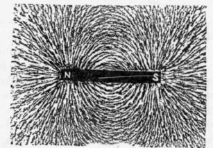
Fig. 20.
This figure may be made permanent by using gummed paper, which may be moistened by steam, after the filings are arranged, and then allowed to dry. When dry, the filings will be firmly attached to the paper by the gum. Attention is directed to the way in which the lines diverge from each pole, and those along the magnet curve toward each other. These lines are known as the " lines of force," and are a visible illustration of these lines, which act in all directions from a magnet.
Other instructive experiments are made by replacing the bar-magnet with the N and S poles of two bar-magnets slightly separated, as shown in Fig. 21; also using the two N poles and a single N pole, and, with the iron tilings, determine the lines of force developed on the sheet of paper. How the lines of force are utilized in dynamo, motor and other electrical devices will be considered later.
In the last chapter we learned that the magnetic polarity, in the several experiments, was dependent on the direction of the current. It is important that this should be clearly understood and remembered by the student. Referring to Fig. 15 and the experiments connected therewith, the following rule, suggested by Ampere, should be memorized: " Suppose a man swimming in the wire with the current, and that he turns his head so as to face the needle, then the N-seeking pole of the needle will be deflected towards his left hand." Another convenient rule, known as the "corkscrew" rule of Maxwell, is, "The direction of the current and that of the resulting magnetic force are related to one another as are the rotation and forward travel of an ordinary (right-hand) corkscrew." (See Fig. 19.)
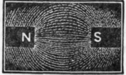
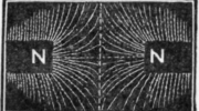
Fig. 21.
The experiments previously described show that the magnetic attraction is variable and dependent upon several factors, which are : a, the amount of the current flowing; b, the number of turns of wire; c, the size of the conductor.
There is a limit, however, beyond which the magnetic force of a coil cannot be developed. This is known as the saturation limit or saturation point.
If a core of soft iron be wound with one layer of wire carrying a current of one ampere, a certain weight of iron may be lifted thereby. If another layer of wire be added, the current may be reduced nearly one-half without diminishing the lifting power. Another layer of wire will enable a still further reduction in the current. Successive layers of wire may be added with proportionate reductions in the current, until eventually the final layers produce little or no addition to the magnetic force developed, because the resistance of the wire equals or exceeds the magnetic force developed. It is because of this fact that the secondary winding of an induction coil cannot be increased indefinitely, but bears a fixed relation to the size of the primary winding and core; hence the expression of " ampere turns" as applied to wiring of electrical devices.
From this also arises the necessity of calculating the relation of battery strength and force, and the number of turns and size of wire. With a battery of high E. M. F., but low current, more turns and finer wire are necessary than with a battery of large current or high amperage, with which fewer turns and larger wire may be used. The saturation capacity of the wire regulates the maximum number of turns to be given a coil.
Though extremely rapid, a certain time is required for magnetic action, and also for demagnetization to take place. If an electro-magnet is to be rapidly excited, it should be short and thick, as the action of such a form is quicker than with a long one. If a strong, slow action is required, a long electro-magnet is the better.
Referring again to Fig. 19, if the iron core be omitted from the coil or spiral of wire, the coil will, when excited by a current, act as an electromagnet, though with much less power than with the core. Such a coil is termed a "solenoid," and will attract and repel other solenoids, electromagnets, and, in fact, present the same phenomena as do electro-magnets. The magnetic field of a solenoid is strongest within the coil, and the core is most strongly magnetized when placed therein, though more or less magnetized whenever within the lines of force of the coil. Certain electrical instruments are simply one solenoid within another. When the interior one is movable, it is termed a " sucking solenoid," the inner one always tending to move into the position in which it best completes the magnetic circuit. If a solenoid be suspended so that it can turn freely, it will, when influenced by a current, set itself in the direction of the magnetic meridian, the same as does an ordinary compass.
Castings for the motor described in the March number are being made, and will be offered as a premium for new subscribers.
Continue to:
My Books

