A Gasolene Touring Car. I. The Gear Case. Continued
Description
This section is from the book "Amateur Work Magazine Vol4". Also available from Amazon: Amateur Work.
A Gasolene Touring Car. I. The Gear Case. Continued
The holes for the various bolts are then laid off on the finished surface of the upper half and drilled from the inside, with the piece resting on its feet. This half is then used as a jig and is laid down on the bottom half, clamped firmly in place and the holes in the lower half drilled by running the drill through the holes in the top. This insures that all holes will be exactly in line and match. The bearing for the nuts should be faced so that the nut will have a good seating. The holes for the bolts securing the case to the frame may also be drilled at this time.
The hole for the gear shifting rod d in the upper half is drilled with a | in. drill, either from the inside, using a small ratchet, or from the outside on the drill press.
On the lower half the same directions apply as to the 8/4 in. hole for the reverse pinion shaft. If drilled on a press a hole should be laid off and drilled in the front of the case to admit a J in. round bar of steel flattened on the end and ground as a flat drill. When this method is used it is well to wait until the shafts or mandrels are in place and then use the small jig shown in Fig. 3 c. The holes in this jig are bored exactly to size, with their location carefully laid off, the piece split, as shown, with a saw, and the screws fitted to clamp the mandrels firmly. Then when the mandrels are babbited in place, this jig is damned to them so that the drill guiding hole comes before the projection e in the lower half of the case. This forms a guide which controlls the action of the drill and insures that the pitch lines of the reverse pinion and meshing gears are exactly in contact.
The case is now ready for the bearings. These are made of Babbitt metal, which is the best metal that can be used in this place, especially since the bearings are subjected to very hard duty. They remain very cool under load and do not grip when heated, as do brass bushings. They have a comparatively long life and are readily replaced by the owner of the machine when badly worn by chipping out the old metal, re-lining the shafts and again pouring in new metal.
Chip and clean the recesses cast in the case so that the metal may have a good hold. Prepare two mandrels about 1 1/2 in. longer than the bearings from the extreme end of the outside to the opposite extreme end of the inner ones and l 1/4 and 1 1/2 in. in diameter, respectively. Polish the bearing portions as smoothly as possible. The extra length over that of the shafts allows the washers to be clamped tightly against the bearings to keep the melted metal in place.
Now make the jig or yoke 6, Fig. 3, by first fitting the two pieces together perfectly, as shown, securing them by two 3-16 in. screws at the ends. The joint must be perfectly straight. Now lay off the holes with centers exactly 3 in. apart and bore to size on the lathe face plate. If the lathe will not swing them, have them bored in some shop, which should cost only a trifle.
When finished two yokes are provided for suspending the mandrels in place and a small 1/8 in. strap secured by three small screws, as shown in Fig. 3 c, will hold the mandrels firmly in place. Now lay the mandrels in position in the upper half of the case and adjust them "accurately parallel with the center line of the case.
Clamp the yokes securely at one end, drill a 3-32 in. hole through the opposite end and flange to take a dowel pin, as shown. Then see that the ends of the bearings are properly dammed with a piece of blotting paper held securely against them by a wooden ring forced over the end of the shaft as in Fig. 3 d, the ends of the bearings having been previously filed smooth and square, and to the same length in both halves that match. Have the metal quite hot and the mandrels smeared with a very thin film of graphite to prevent the Babbitt metal from adhering thereto. When cold remove the mandrels and file off the top of the Babbitt metal until flush with the joint of the case. Each half is similarly babbitted.
Before pouring the other half, lay them together and put two bolts through opposite holes. Then run the 3-32 in. .drill through the undrilled flange, using the already drilled hole as a guide. Now reverse the positions of the yokes on the mandrels so that they may be used on the same ends in each case, and pour the bearings in the remaining half. The dowel pins will thus locate the position of the shafts exactly, so that when the two halves are bolted together the bearing will be a truly cylindrical hole, and the pressure of the bolt will not draw the halves to one side or the other, thus cramping the shaft.
The shaft for the large bevel gear and sprocket may now be linned up. In lining up this shaft the other shaft with its bevel pinion should be in place so that the two gears may be made to mesh exactly. It may be supported in position by two centers made of 1/8 in. rod fitted in two blocks, as shown in the small sketch, Fig. 3e. This enables the two shafts to be turned while setting, and the exact position determined. Of course when the case is machined the trial setting is unnecessary, but for the amateur this method is both quick and accurate. When properly set, dam the bearings with putty and pour in the hot metal, having previously covered the shaft with graphite.
Now chip a small, half round groove, opened at the inside end, in the bottom of each bearing, Fig. 3, f, so that the oil will drain to the inside of the case instead of running outside. This is in the bearings of the bottom half only.
In the bearings of the upper half chip a similar groove, but closed at each end. Then drill a 1/4 in. hole through to the inside, as shown, Fig. 3 g. A 1/4 in. brass tube leads into this from the oil trough on the side, thus flooding the bearings with oil. A similar device is used to oil the bevel gear shaft, as shown. The troughs are simply strips of brass bent into a "V" shape and secured to the side by screws passing through. They catch the oil draining down from the inclined top where it is splashed by the gears.
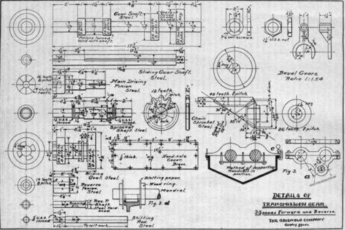
The machine work on the other part requires no particular description, as it is very simple and the gears can be cut at a shop fitted for such work, or they may be purchased already cut. For those not wishing to go to the expense of cut gears, a set of cast gears has been prepared which can be made to run very smoothly by finishing the working faces of the teeth with a file. Of course cast teeth do not work as well as cut, neither are they as strong, but for a light car they do quite well and are cheap. The various details of the gear are shown in Fig. 4.
The length of the shaft attached to the clutch shaft is merely long enough to take a muff coupling, the intermediate length to the clutch being fitted when the gear and engine are in place.
Continue to:
My Books

