A Sensitive Galvanometer
Description
This section is from the book "Amateur Work Magazine Vol4". Also available from Amazon: Amateur Work.
A Sensitive Galvanometer
R. G. Griswold
In measurements of resistance by means of the Wheatstone bridge, to be described later, it is essential that the galvanometer used should be very sensitive, so that it may detect either the presence of an extremely small current or indicate the slightest variation in the strength of a current flowing. One of the most sensitive galvanometers which lends itself to easy construction is the astatic type, the magnetic system of which consists of two magnetic needles rigidly mounted on one vertical axis, with poles reversed. Its sensibility depends upon three conditions: Highly magnetized needles, small controlling force, and a large number of turns on the galvanometer bobbin. Two side elevations of this instrument are shown in Fig. 1, and a plan view in Fig. 2.
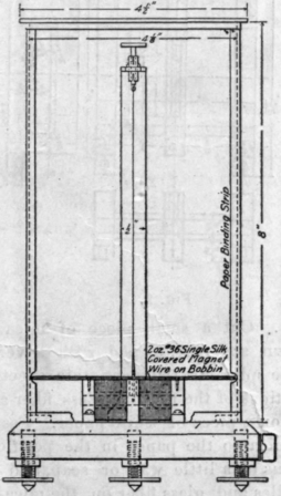
The bobbin, Fig. 3, upon which the wire is wound, should be made of some fine-grained hard wood, such as cherry. It can be worked out to the best advantage with a fret saw and a file. The construction will be greatly facilitated if the form is divided on the line a b and then glued together after the two parts are completed. Give it one coat of shellac and see thatthe space in which the lower needle swings is smooth and free from hairs from the brush, pieces of lint or other small obstructions that would interfere with the delicate action of the suspended system. Wind the bobbin with 2 ounces of No. 36 single silk-covered magnet wire, winding one side full first and then the other, so that the current will flow in the same direction about both coils.
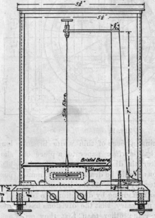
Mount the coil upon the base, carrying the wires from the bobbin coil terminals down through holes to grooves cut in the bottom of the base, and thence to the binding screws on the side to the clips of which they are soldered. The dial
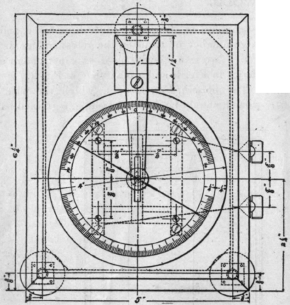
Fig. 2.
is made by gluing a piece of thin white bristol board or other hard-surface paper to a piece of sheet zinc. After the dial is cut to size the circles and divisions should be drawn thereon, numbering the latter by tens. As the instrument is not intended for measuring by deflections in degrees, it is not necessary that the divisions have any particular value other than that they are equal. Fasten the dial to the bobbin by the screws shown so that the center of the dial coincides exactly with the center of the bobbin.
The vertical post is made of wood and has mounted at the top a brass arm, Fig. 4 a, carrying at its end an adjustment device for the suspension fiber. A small piece of brass tubing which just fits the brass rod of the hook pin, is soldered in the end of the arm, and fine saw slits are cut at right angles in the top and bottom to permit a slight binding on the pin by squeezing them together slightly. The hook pin, Fig. 4 b, should work smoothly, but be held with sufficient friction to stay in any position.
The magnetic system, Fig. 5 a, is composed of four very fine sewing needles and a glass fibre mounted between two very thin pieces of mica by means of shellac. Secure four of the finest sewing needles possible, and file off the points and heads until they are 1 in. long. Get from some chemist or druggist a small piece of glass tubing, say 2 or 3 inches long. Heat about an inch of it in the middle in a gas flame until very soft and quickly pull it out at arm's length, which will result in a very fine thread of glass from the thinnest straight portion of which cut a piece 3 1/2 in.
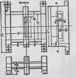
Fig. 3.
long. Cut a small piece of mica to the shape shown at b, Fig. 5, and with a very thin knife blade split off two very thin sheets. Draw the positions of the needles, glass fiber and mica stirrup on a piece of white paper. Fasten one strip of mica to the paper in the position drawn, by means of a little wax or soap, and then lay the needles and glass fiber on the mica in their respective positions, having first put a small drop of shellac on the spots where they cross the mica. Put a small drop of shellac on top of the needles and lay the remaining piece of mica on them, placing a small weight on it until the shellac has dried. Fasten the silk suspension fiber in the pointed end of the stirrup in the same manner, raising the lower side of the stirrup up by means of a piece of paper until the fiber is on a center line passing through the center of the needles. A small weight will serve to keep the two pieces of mica together until they have been firmly cement-ed to the fiber. Fig. 5 c, shows the end view of this stirrup drawn to a larger scale.
The silk fiber can best be obtained from a wire wound silk banjo bass string. By unwinding the wire from the string a long, fine fiber can be drawn out, which, being unspun, will have an equal torsional effect for either direction of swing from the zero point. The balance of the silk, as well as the fine wire, should be wrapped on a card for future use.
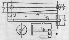
Fig. 4.
The levelling screws, Fig. 7 a, are made by forcing the unthreaded end of the screw into the disk b, soldering if necessary. The square piece c is threaded and fastened to the bottom of the base, 1/4 in. holes being bored into the wood to accommodate the end of the screw.
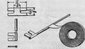
Fig. 6.
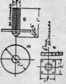
Fig. 7.
The instrument being finished and assembled, it is now ready to receive the magnetic system. To magnetize the needles, make an electromagnet by wrapping about 100 turns of No. 22 magnet wire around a quarter-inch rod, 2 in. long. Touch the end marked N, Fig. 5 a, of the upper set of needles with one end of the magnet for one minute while the current is passing, and then with the same end of the magnet touch the end marked A7" of the lower set of needles for the same time and with the same amount of current. This will strongly magnetize the needles so that the corresponing ends of the two sets will have opposite polarities, and as the north-seeking end of one set is almost if not quite counterbalanced by that of the other set, the directive force of the system will be very small.
Adjust the hook so that it projects equally on each side of the split tube. Insert the lower needles in the slot in the dial and pass the fiber through the slot in the hook from the center outwards so that it will hang from the center of the
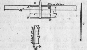
Fig. 5.
rod and not from a point outside of the center. Adjust the length of the fiber until the lower needles hang exactly in the center of the coils when looking through from the side and fasten to the hook with a small drop of shellac. As it is extremely difficult to make two sets of needles that exactly neutralize each other, one set will direct the system in a north-and-south direction and the instrument should be so placed that when the needle is at rest the pointer stands exactly over zero of the scale, and the axis of the coil has an east-and-west direction. The levelling screws will enable the galvanometer to be so adjusted that the pointer lies on both zeros of the scale and the center of the mica stirrup corresponds with the center of the dial. When the pointer is at rest on the zero division, give it a slight impulse and note whether it swings to the same division on either side of zero. If not, the fibre may have a slight twist which may be removed by turning the hook one way or the other until the deflections of the pointer are equal with respect to zero.
The galvanometer should now be provided with a glass case to protect it from dust and air currents. This case is made from five pieces of clear window glass, bound together at the edges with strips of gummed, black paper, such as is used for binding magic lantern slides and passa-partout pictures. Four small triangular blocks are glued to the base to prevent the case from slipping off. Great care should be taken to thoroughly insulate the bobbin wires where they pass through the base by making a small tube of paper to line the holes. Thoroughly coat the grooves underneath with shellac before the wires are put in and then give them a good coat. In instruments where such high resistance windings are used, small leakages of . current that might occur across a moist surface or a thin layer of dust would so reduce the efficiency that proper indica-cations will not be made. For this reason all places of probable leakage should be given good coats of shellac spirit and baked, if possible. Shellac is one of the best insulators and is easily applied.
In connecting various electrical instruments together, much annoyance is caused by the stiffness of wires of sufficient cross section to carry the current without appreciable loss. The connect ing wires can be made of flexible lamp cord or several small copper wires, say No. 32 gauge, twisted together and insulated by winding tape around them. The ends should be soldered into a copper clip, as shown in Fig. 6, which is easily slipped under the head of the binding screw and insures good contact. If several of these connecting wires are made of different lengths much time will be saved during experiments in making connections.
A number of the clips may be made at once by clamping several pieces of sheet copper in a vise and working out the screw slots of all at the same time. Tin them on the inside of the bend before winding about the wire, by rubbing a hot soldering iron over the spot with rosin as a flux. Then tin the end of the wires. When the clip has been bent around the wire, squeeze it in the vise so as to make it lie close. Heat the tinned portion in a flame, when it will be firmly soldered to the wire. The tape may be secured from any electrical house for a few cents.
Continue to:
My Books

