An Easily Built Power Launch. Continued
Description
This section is from the book "Amateur Work Magazine Vol5". Also available from Amazon: Amateur Work.
An Easily Built Power Launch. Continued
The covering boards (marked cover board in Fig. 16) are first put on. These are shaped by laying the material on top and marking in from below. The covering boards are the full width from the outside of sheer-streak to the inside of the coaming.plate, alongside of the cock-pit. They may be narrowed up where they enclose the deck at the ends, as shown in Fig. 16.
The decks may be laid of any fancy wood, either in alternate strips of a dark and a light color, or all of the same.
When laid in this way the decks will have to be calked. A good way to calk the deck is to use a heavy piece of cotton twine. Lay it in the seams and tap it snugly down with a putty knife. The seams should then be payed off with varnish or wood filler and then puttied.
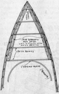
Fig. 15.
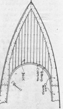
Fig. 16.
The two side pieces that form the coaming are cut out, fitted in place, and fastened to the clamp as shown in Fig. 11, using 1 1/4 in. screws 12 in. apart. The end pieces of the coaming are simply gotten out straight and fitted across the end. When put in these end pieces should be about 9 in. wide. After they are fastened, they may be scribed to conform to the height of the coaming and the crown of the deck. The corners of the coaming are reinforced by fitting a piece of quarter-round in each, on the inside.
The fender-wale is a half-round strip that is put on the outside, with its top edge flush with the top edge of the boat. It is fastened in place with 6-penny casing nails. See Fig. 12.
The engine bed is usually made of two pieces of oak, 2 in. thick. These run fore and aft and are notched over the floor timbers. The top of the bed timbers are dressed down to conform with the angle of the shaft. The size of these timbers and their distance apart will, of course, vary with different engines. The bed timbers are fastened to the bottom with 1 7/8 in. screws, put up through the bottom into the bed timbers.
The shafting is cut out of 3 in. oak, and is fastened in place on the keel at the location shown on the keel pattern. The shaft log is fitted down onto the keel. The floor timbers are cut out to allow the shafting-log to go down on the keel. Fit the shaft-log to the keel and fasten it in place with 1 1/2 in. screws, up through the bottom into the shaft-log. Before putting in the shaft-log, fit a piece of canvas, laid in white lead paint, between it and the keel, and when putting in the screws, be careful not to get any of them in the way of the shaft hole.
Fig. 17 shows a simple method of making a guide for holding auger so as to bore shaft log straight. Two guides are fastened, one on each side of stern post, with a notched cross-piece connecting them. The notch in cross-piece will, of course, be in line of shaft hole. The shaft hole should be bored with a ship auger, which must be removed every few turns to clean out shavings. Sometimes a small hole is first bored out and then burned out to desired size with a red hot iron. Should the auger run too far out of line, stop boring and start again from other end of pipe log, then when the holes intersect they may be straighened by burning. If for any good reason it is desired to bore a hole over where a hole has already been started, first plug the original boring.
It is a good plan for the amateur to bore the shaft log before it is set up in the frame. The auger guide may be used same as described, then when the frame is set up the stern-post may be bored true by passing the auger through the shaft log and boring from the inside.
Another way of making the hole in shaft log is to make the log in two pieces by dividing it lengthwise in the center, and the hole may then be worked out with a mallet and chisel, half of the hole in each piece. When so made the log should be bolted together, with a piece of canvas laid in white lead paint between the parts.
The rudder port is a piece of gas pipe that is threaded into the fashion-piece and extends to the top of the deck; or when the tiller is under the deck, the upper end of the rudder port ends just below the tiller. The diameter of the interior) of the rudder port should be 1/4 in. larger than the diameter of the rudder post.
The shoe is a flat piece of iron that holds the lower end of the rudder and is bolted directly to the keel. The shoe should clear the propeller wheel an inch, and when the shoe will not give this clearance straight out from the keel, it may be bent or an extension wedge-shaped skeg may be used to lower it. The end of the shoe should be turned over and a bent key put into the end of the rudder post to prevent its unshipping.
The location of the rudder port and the end of the shoe should be far enough back from the stern post to allow an inch or more clearance between the rudder and the propeller wheel. The rudder post should stand parallel to the stern post.
Cut the rudder out to shape and rivet it to the rudder post. The post may be in two pieces, or the post may be in one piece and the rudder blade in two sheets fastened together with the post riveted between.
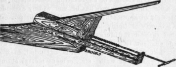
Fig. 17.
The upper end of the rudder post is forged square to fit the tiller. On small launches the tiller is usually connected with cotton rope. This runs through blocks and fair leaders around the coaming. When the tiller is on deck, four cheek halyard blocks are used at the four corners of the coaming, and common brass eyelets for fair leadors alongside the coaming. When the tiller is below deck, a common block without becket should be used at the four corners. This block should be fastened by a staple to the clamp to allow it to swing freely. When the steering wheel is used it will of course be fastened to the forward end of the coaming.
The seats in this boat had best be put athwartships, the same as a row boat, they may be located to suit owner's taste. The seats should be made of 7/8 in. lumber and be from 12 to 14 in. wide. The sides on the inside may be paneled up, or finished with narrow strips, or left as it is and painted.
To finish the outside of the boat, set in all nails and plane and sand paper smooth; then give a priming coat of paint, putty all nails heads; then give two or three coats of paint.
Continue to:
My Books

