Elements Of Dynamo Design
Description
This section is from the book "Amateur Work Magazine Vol6". Also available from Amazon: Amateur Work.
Elements Of Dynamo Design
Ira M. Cushing
The young Electrical Engineer, after he has passed the age of batteries, electric bells, miniature motors and the like, has a very natural ambition to design and build a piece of electrical apparatus that may be put to practical use. In looking over the field he finds a machine which at once seems to be the most important one for the production of the electric current, and also seems to be simple enough for his limited ability, to construct.
This machine is the dynamo. It is simplicity itself:-A substantial frame of iron with copper wire wound upon it and a revolving part, also of iron, and some wire coiled on it. The young engineer is very much discouraged, however, when he begins to read various books on Dynamo Design, and is bewildered with the vast array of formulae and theory. The object which the author has in mind in writing this series of articles, is to aid the beginner in his study of this subject by stating the principles in as clear a way as posible, and by presenting the formulae for the simpler and most common form of generators in such terms that they can be readily understood and applied.
The reader must remember that the subject is very broad- and full of infinite and intricate detail into which it is imposible to enter in the scope of these articles. It will be necessary, therefore, to make statements without proofs of their truth, but which can be verified by a further study of the subject in other publications. A list of books will be given at the end of the series, the perusal of which, if not the study, we recommend to the student after he has mastered this treatise.
Some of the formulae given have figures in them. They remain the same for any value of the letters, and are therefore called constants. There- is a reason for these and the young student must now take them for granted. A study of the more exhaustive books will explain their derivation.
The student should be warned at the start of many of the pitfalls along the path of Dynamo Design. One of the greatest sources of error arises from the fact that most, if not all, the formulae were worked out on the C. G. S. (centimeter-gram-second) system, and must be transposed into the inch-pound-second system, which prevails in this country. The changing is very confusing, and unless care is exercised the terms are mixed and inaccuracy with bad results follow. In this work, however, the formulae are given for inches and no tables or formulae are given for dimensions in the metric system. The latter may be found, however, in other works to which the reader is referred.
Another idea to be noted is that dynamo design is, and is not, an exact science. It is exact in so far as the formulae themselves are concerned, but when it comes to the substitution of numbers for the letters, it becomes a matter of individual judgement or engineering how to choose. The reason for variations or doubt is that the quality of material used varies greatly. For illustration, the ability of iron to carry magnestism varies in different parts even of the same piece.
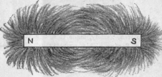
Fig. 1.
The design of the mechanical parts of the dynamo is more a matter of personal engineering than the mere use of formulae. The shape of the frame, the proportioning of the parts one to another, are all matters requiring a personal judgement. Before designing a dynamo it would be well for the novice to study carefully all the different machines, large or small, he can find; the dynamos themselves if possible, but lacking these all the illustrations he can obtain. Find out, if possible, why one is more particularly adapted to a certain kind of work than another; examine critically the mechanical design. The controlling idea should be to design a machine as simple as posible which will perform its work satisfactorily. The revolving parts should be light but substantially built, and designed with a view to withstanding the centrifugal force exerted.
Magnetism performs a very important function in the generation of electricity in a dynamo, and for this reason its principles should be thoroughly understood at the outset.
The name magnet was first given to an iron ore, found at Magnesia in Asia Minor, having the peculiar property of attracting to itself other pieces of iron. Further experiments showed that if a piece of this ore was suspended free, the same end always pointed towards the north. It was also found that a piece of ordinary iron, after being rubbed with the magnet ore, had the same characteristics. The end, therefore, pointing toward the north was supposed to contain "north seeking magnetism" and similarly the other end "south seeking magnetism." By common usage, however, this • has been shortened to "North pole" and "South pole." These two poles are inseparable. It makes no difference how many times a magnet may be cut into parts, each part is found to have a North and South pole.
Many years later it was discovered that a current of electricity passing, by means of a number of turns of wire, around a piece of soft iron, produced the same
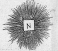
Fig. 2. effect in the iron, namely, made it a magnet while the current was flowing. This property of the electric current has made posible the size and efficiency of the present dynamo.
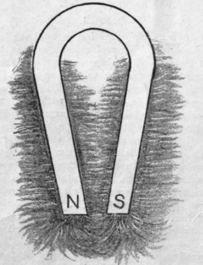
Fig. 3.
It is very evident that a power comes from the poles of a magnet. In order to assist in calculations scientists have assumed that this power eminates in invisible lines called "Lines of force." The number of lines must be nearly infinite and therefore, to further simplify the mathematical work an arbitrary value of one line per unit area has been assumed. These lines of force lie in even, closed curves stretching between the north and south poles. The direction in which they travel cannot be determined, but has been assumed as being from the north to the south pole.
The presence of these lines of force can very easily be shown. Place a bar magnet on the table and cover it with a piece of smooth paper. Sprinkle some iron filings over it and tap the paper gently. The filings will arrange themselves end to end and form smooth curves from pole to pole of the magnet as shown in Fig. 1. If the magnet be placed with its axis vertical to the paper, one pole touching it underneath, and the filings put on, the result will be as in Fig. 2. Fig. 1 shows that the lines of force pass from pole to pole, Fig. 2 shows that they eminate in all directions from the poles. Another point to be illustrated could best be shown by first placing a horseshoe magnet beneath the paper. The irons filings show quite an intense "field of force" between the ends or poles, diminishing as you go down the legs. Now place in position the keeper or "armature," as the piece of iron usually kept across the poles is called, and again sprinkle on the filings. Any rearrangement of the particles is hardly noticeable. This would indicate that the iron is so greatly a better conductor of magnetism that the keeper has taken practically all the lines of force. See Figs. 3 and 4. A particular point which should be noted is that no lines of force cross, all are either parallel or diverging.
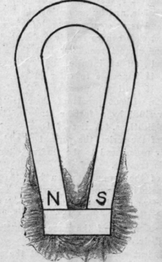
Fig. 4. The discovery has been made, by experiment, that a current passing through several turns of wire about an iron core will produce these same lines of force and further that the magnetizing power of the coil or force exerted by the coil was proportional to both the number of turns of wire and the intensity of the current. Let I represent amperes, S equal turns, k, a constant (a number whose value is the same for all values of the other letters) and H equal magnetizing power, then
H = KIS ( 1 ) This is the force exerted at a point. To produce work, this force must be expended through a measurable distance as, for example, around a horseshoe magnet. It has been found that the resulting force diminishes • in proportion as the length increases. Hence, let L equal the length of the magnetic circuit, then formula 1 will become
H = k I.S / S (2)
This is true for all coils, or solinoids of moderate length. In coils of excessive length some of the lines of force pass out before reaching the last turns thus reducing the power at the ends. With the length given in inches k will equal 0.3132.
The expression I.S. is called "Ampere turns." It has been found experimentally that the value of H in ( 2 ) does not vary with the changes in I and S, provided their product remains the same. In other words, if I.S. equals 50, it makes no difference in the resulting magnetizing force whether one ampere flowed through 50 turns, or 50 amperes passed through one turn. This principle becomes very useful in dynamo design and should constantly be kept in mind by the student.
Continue to:
My Books

