Drawing Gear Wheels. Part 3
Description
This section is from the book "Mechanical Drawing Self-Taught", by Joshua Rose. Also available from Amazon: Mechanical Drawing Self-Taught.
Drawing Gear Wheels. Part 3
To obtain the arcs for the other end of the tooth, draw line M M parallel to line J K; set the compasses to the radius R L, and from P, as a centre, draw the pitch circle k. For the depth of the tooth draw the dotted line p, meeting the circle h and the point W. A similar line, from i to W, will give the height of the tooth at its inner end. Then the tooth curves may be drawn on these three arcs, k, l, m, in the same as if they were for a spur wheel.
Similarly for the pitch circle of the inner and small end of the pinion teeth, set the compasses to radius S L, and from Q as a centre mark the pitch circle d. Outside of d mark e for the height above pitch lines of the tooth, and inside of d mark the arc f for the depth below pitch line of the tooth at that end. The distance between the dotted lines as p, represents the full height of the tooth; hence h meets p, which is the root of the tooth on the large wheel. To give clearance and prevent the tops of the teeth on one wheel from bearing against the bottoms of the spaces in the other wheel, the point of the pinion teeth is marked below; thus arc b does not meet h or p, but is short to the amount of clearance. Having obtained the arcs d, e, f, the curves may be marked thereon as for a spur wheel. A tooth thus marked is shown at x, and from its curves between b and c, a template may be made for the large diameter or outer end of the pinion teeth. Similarly for the wheel C the outer end curves are marked on the arcs g, h, i, and those for the other end of the tooth are marked between the arcs l, m.
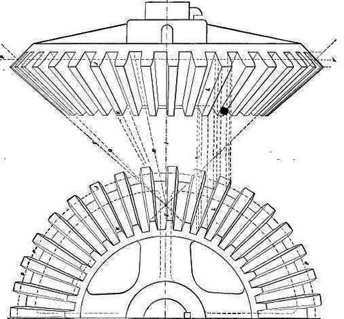
Fig. 243. (Page 207.)
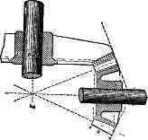
Fig. 244.
Figure 243 represents a drawing of one-half of a bevil gear, and an edge view projected from the same. The point E corresponds to point E in Figure 241, or W in 242. The line F shows that the top surface of the teeth points to E. Line G shows that the pitch line of each tooth points to E, and lines H show that the bottom of the surface of a space also points to E. Line 1 shows that the sides of each tooth point to E. And it follows that the outer end of a tooth is both higher or deeper and also thicker than its inner end; thus J is thicker and deeper than end K of the tooth. Lines F G, representing the top and bottom of a tooth in Figure 243, obviously correspond to dotted lines p in Figure 242. The outer and inner ends of the teeth in the edge view are projected from the outer and inner ends in the face view, as is shown by the dotted lines carried from tooth L in the face view, to tooth L in the edge view, and it is obvious from what has been said that in drawing the lines for the tooth in the edge view they will point to the centre E.
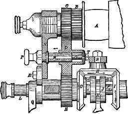
Fig. 245.
To save work in drawing bevil gear wheels, they are sometimes drawn in section or in outline only; thus in Figure 244 is shown a pair of bevil wheels shown in section, and in Figure 245 is a drawing of a part of an Ames lathe feed motion. B C D and E are spur gears, while G H and I are bevil gears, the cone surface on which the teeth lie being left blank, save at the edges where a tooth is in each case drawn in. Wheel D is shown in section so as to show the means by which it may be moved out of gear with C and E. Small bevil gears may also be represented by simple line shading; thus in Figure 247 the two bodies A and C would readily be understood to be a bevil gear and pinion. Similarly small spur wheels
may be represented by simple circles in a side view and by line shading in an edge view; thus it would answer every practical purpose if such small wheels as in Figures 246 and 247 at D, F, G, K, P, H, I and J, were drawn as shown. The pitch circles, however, are usually drawn in red ink to distinguish them.
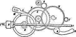
Fig. 246.
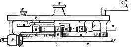
Fig. 247.
In Figure 248 is an example in which part of the gear is shown with teeth in, and the remainder is illustrated by circles.
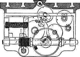
Fig. 248.
In Figure 250 is a drawing of part of the feed motions of a Niles Tool Works horizontal boring mill, Figure 251 being an end view of the same, f is a friction disk, and g a friction pinion, g' is a rack, F is a feed-screw, p is a bevil pinion, and q a bevil wheel; i, m, o, are gear wheels, and J a worm operating a worm-pinion and the gears shown.
Figure 249 represents three bevil gears, the upper of which is line shaded, forming an excellent example for the student to copy.
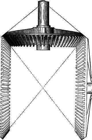
Fig. 249. (Page 210.)
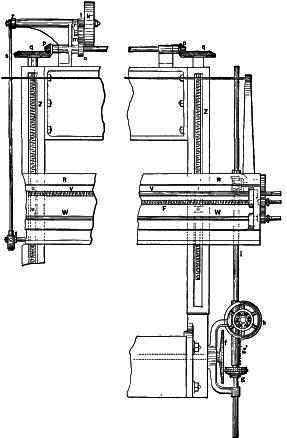
Fig. 250.
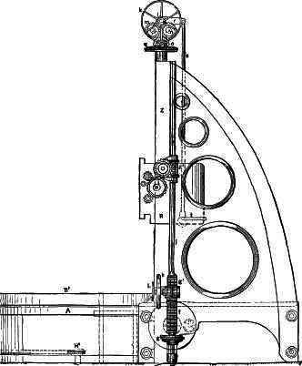
Fig. 251. (Page 209.)
Continue to:
My Books

