Screw Threads And Spirals. Continued
Description
This section is from the book "Mechanical Drawing Self-Taught", by Joshua Rose. Also available from Amazon: Mechanical Drawing Self-Taught.
Screw Threads And Spirals. Continued
For the bottoms of the thread, lines are similarly drawn, as from i' to meet i, where dot I is marked. J is got from j' and j, while K is got from the intersection of k' with k, and so on, the dots from I to O being those through which a curve is drawn for the bottom of the thread, and from this curve a template also may be made to mark all the thread bottoms. We have in our example used eight points of division in each half-circle, but either more or less points maybe used, the only requisite being that the pitch of the thread must be divided into as many divisions as the two half-circles are. But it is not absolutely necessary that both half-circles be divided into the same number of equal divisions. Thus, suppose the large half-circle were divided into ten divisions, then instead of the first half of the pitch being divided into eight (as from a to h) it would require to have ten lines. But the inner half-circle may have eight only, as in our example. It is more convenient, however, to use the same number of divisions for both circles, so that they may both be divided together by lines radiating from the centre. The more the points of division, the greater number of points to draw the curves through; hence it is desirable to have as many as possible, which is governed by the pitch of the thread, it being obvious that the finer the pitch the less the number of distinct and clear divisions it is practicable to divide it into. In our example the angles of the thread are spread out to cause these lines to be thrown further apart than they would be in a bolt of that diameter; hence it will be seen that in threads of but two or three inches in diameter the lines would fall very close together, and would require to be drawn finely and with care to keep them distinct.
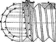
Fig. 208 a.
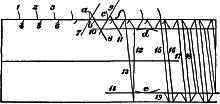
Fig. 209.
The curves for a United States standard form of thread are obtained in the same manner as from the V thread in Figure 208, but the thread itself is more difficult to draw. The construction of this thread is shown in Figure 208, it having a flat place at the top and at the bottom of the thread. A common V thread has its sides at an angle of 60 degrees, one to the other, the top and bottom meeting in a point. The United States standard is obtained from drawing a common V thread and dividing its depth into eight equal divisions, as at x, in Figure 208 a, and cutting off one of these divisions at the top and filling in one at the bottom to form flat places, as shown in the figure. But the thread cannot be sketched on a bolt by this means unless temporary lines are used to get the thread from, these temporary lines being drawn to represent a bolt one-fourth the depth of the thread too large in diameter. Thus, in Figure 208 a, it is seen that cutting off one-eighth the depth of the thread reduces the diameter of the thread. It is necessary, then, to draw the flat place on top of the thread first, the order of procedure being shown in Figure 209. The lines for the full diameter of the thread being drawn, the pitch is stepped off by arcs, as 1, 2, 3, etc.; and from these, arcs, as 4, 5, 6, etc., are marked for the width of the flat places at the tops of the threads. Then one side of the thread is marked off by lines, as 7, which meet the arcs 1, 2, 3, etc., as at a, c, etc. Similar lines, as 8 and 9, are marked for the other side of the thread, these lines, 7, 8 and 9, projecting until they cross each other. Line 10 is then drawn, making a flat place at the bottom of the thread equal in width to that at the top. Line 12 is then drawn square across the bolt, starting from the bottom of the thread, and line 13 is drawn starting from the corner f on one side of the thread and meeting line 12 on the other side of the thread, which gives the angle for the tops of the thread. The depth of the thread may then be marked on the other side of the bolt by the arcs d and e, and the line 14. The tops of all the threads may then be drawn in, as by lines 15, 16, 17 and 18, and by lines, as 19, etc., the thread sides may be drawn on the other side of the bolt. All that remains is to join the bottoms of the threads by lines across the bolt, and the pencil lines will be complete, ready to ink in. If the thread is to be shown curved instead of drawn straight across, the curve may be obtained by the construction in Figure 208, which is similar to that in Figure 207, except that while the pitch is divided off into 16 divisions, the whole of these 16 divisions are not used to get the curves, some of them being used twice over; thus for the bottom the eight divisions from b to i are used, while for the tops the eight from g to o are used. Hence g, h and i are used for getting both curves, the divisions from a to b and from o to p being taken up by the flat top and bottom of the thread. It will be noted that in Figure 207, the top of the thread is drawn first, while in Figure 208 the bottom is drawn first, and that in the latter (for the U.S. standard) the pitch is marked from centre to centre of the flats of the thread.
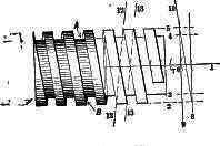
Fig. 210.
To draw a square thread the pencil lines are marked in the order shown in Figure 210, in which 1 represents the centre line and 2, 3, 4 and 5, the diameter and depth of the thread. The pitch of the thread is marked off by arcs, as 6, 7, etc., or by laying a rule directly on the centre line and marking with a lead pencil. To obtain the slant of the thread, lines 8 and 9 are drawn, and from these line 10, touching 8 and 9 where they meet lines 2 and 5; the threads may then be drawn in from the arcs as 6, 7, etc. The side of the thread will show at the top and the bottom as at A B, because of the coarse pitch and the thread on the other or unseen side of the bolt slants, as denoted by the lines 12, 13; and hence to draw the sides A B, the triangle must be set from one thread to the next on the opposite side of the bolt, as denoted by the dotted lines 12 and 13.
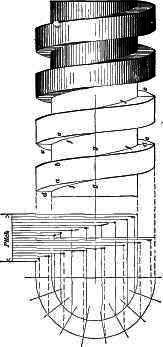
Fig. 211.
If the curves of the thread are to be drawn in, they may be obtained as in Figure 211, which is substantially the same as described for a V thread. The curves f, representing the sides of the thread, terminate at the centre line g, and the curves e are equidistant with the curves c from the vertical lines d. As the curves f above the line are the same as f below the line, the template for f need not be made to extend the whole distance across, but one-half only; as is shown by the dotted curve g, in the construction for finding the curve for square-threaded nuts in Figure 212.
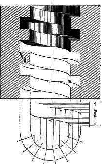
Fig. 212.
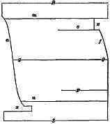
Fig. 213.
A specimen of the form of template for drawing these curves is shown in Figure 213; g g, is the centre line parallel to the edges R, S; lines m, n, represent the diameter of the thread at the top, and o, p, that at the bottom or root; edge a is formed to the points (found by the constructions in the figures as already explained) for the tops of the thread, and edge f is so formed for the curve at the thread bottoms. The edge, as S or R, is laid against the square-blade to steady it while drawing in the curves. It may be noted, however, that since the curve is the same below the centre line as it is above, the template may be made to serve for one-half the thread diameter, as at f, where it is made from o to g, only being turned upside down to draw the other half of the curve; the notches cut out at x, x, are merely to let the pencil-lines in the drawing show plainly when setting the template.
When the thread of a nut is shown in section, it slants in the opposite direction to that which appears on the bolt-thread, because it shows the thread that fits to the opposite side of the bolt, which, therefore, slants in the opposite direction, as shown by the lines 12 and 13 in Figure 210.
In a top or end view of a nut the thread depth is usually shown by a simple circle, as in Figure 214.

Fig. 214.
To draw a spiral spring, draw the centre line A, and lines B, C, Figure 215, distant apart the diameter the spring is to be less the diameter of the wire of which it is to be made. On the centre line A mark two lines a b, c d, representing the pitch of the spring. Divide the distance between a and b into four equal divisions, as by lines 1, 2, 3, letting line 3 meet line B. Line e meeting the centre line at line a, and the line B at its intersection with line 3, is the angle of the coil on one side of the spring; hence it may be marked in at all the locations, as at e f, etc. These lines give at their intersections with the lines C and B the centres for the half circles g, which being drawn, the sides h, i, j, k, etc., of the spring, may all be marked in. By the lines m, n, o, p, the other sides of the spring may be marked in.
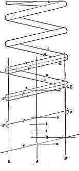
Fig. 215.
The end of the spring is usually marked straight across, as at L. If it is required to draw the coils curved instead of straight across, a template must be made, the curve being obtained as already described for threads. It may be pointed out, however, that to obtain as accurate a division as possible of the lines that divide the pitch, the pitch may be divided upon a diagonal line, as F, Figure 216, which will greatly facilitate the operation.
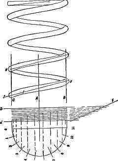
Fig. 216.
Before going into projections it may be as well to give some examples for practice.
Continue to:
My Books

