Compound Leverage. Compound Common Levers
Description
This section is from the book "Scientific American Reference Book. A Manual for the Office, Household and Shop", by Albert A. Hopkins, A. Russell Bond. Also available from Amazon: Scientific American Reference Book.
Compound Leverage. Compound Common Levers

Compound Revolving Levers

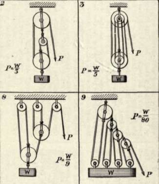
Compound Pulleys
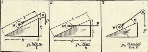
Inclined Plane. Simple Inclined Plane
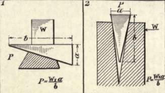
Wedge Or Moveable Inclined Plane
Screw Or Revolving Inclined Plane

Copyright, 1904, by Munn & Co.
Machine Elements II.
in which P represents the power, W the weight, and n the number of ropes used. The general formula for the arrangement shown
W in Figure 7 is P=-W/2n. The general formula for the arrangement shown in Figure 8 is
W P = W/3n. The general formula for the arrange-
W ment shown in Figure 9 is P = W/3n•
There are three general classes of inclined planes, the simple inclined plane, the wedge or movable inclined plane, and the screw or revolving inclined plane. There are three general types of simple inclined planes, as illustrated. 1st. That in which the power acts in a direction parallel with the inclined face of the inclined plane. 2d. That in which the power acts parallel with the base of the inclined plane. 3d. That in which the power acts at an angle both to the face and to the base of the inclined plane. The formulae for determining the mechanical advantage secured by the different forms of inclined planes are given in the illustration. In the third type of inclined plane the relation of power to weight changes as the weight is drawn up the plane, owing to the fact that the angle B becomes gradually larger.
There are two types of wedges, the single wedge and the double wedge. The latter is the more common type.
Under revolving inclined planes we have the screw together with the cam (not illustrated here), which are more commonly used in machinery than any other type of inclined plane.
Continue to:
My Books

