A New Reflecting Galvanometer
Description
This section is from "Scientific American Supplement". Also available from Amazon: Scientific American Reference Book.
A New Reflecting Galvanometer
Fig. 1 shows an elevation of the instrument and a horizontal section of the bobbins. Two pairs of bobbins, cc, cc, are so arranged that the axes of each pair are parallel and in the same vertical plane. Each pair is supported by a vertical brass plate, and the two plates make an angle of about 106° with each other, so that the planes containing the axes of the bobbins make an angle of about 74°. Two horseshoe magnets, m m, made of 1/25 inch steel wire, are connected by a very light piece of aluminum and placed at such a distance from each other that, on being suspended, the two branches of each of the magnets shall freely enter the respective bores of the two bobbins fixed upon the same plate, and, when the whole system is in equilibrium and the bobbins free from current, the two branches of each of the magnets shall nearly coincide with the axes of such bores. The magnets are not plane, but are curved so as to form portions of a vertical cylinder whose axis coincides with the direction of the suspension wire, and to which the axes of the bobbins are tangent at their center, approximately to the points where the poles of the magnets are situated.
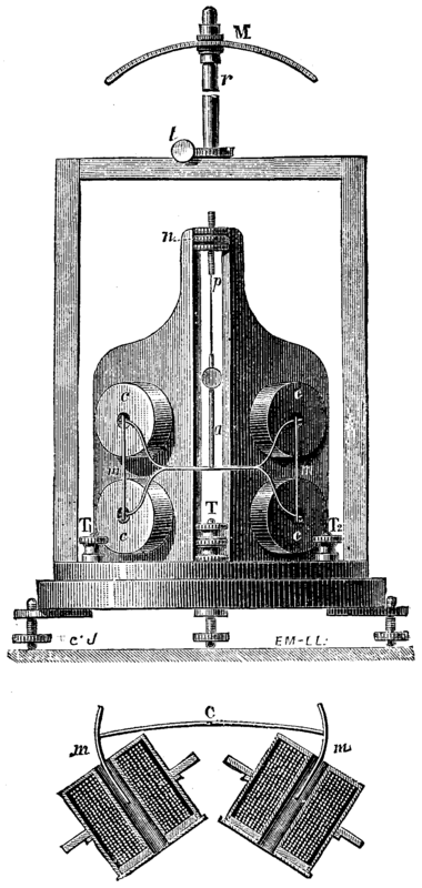
FIG. 1. GRAY'S GALVANOMETER.
The needles have been given this form so that their extremities shall not touch the sides of the bore during considerable deflections.
In the instrument which the inventors, Messrs. T. & A. Gray, used in their experiments upon the resistance of glass, the needles were arranged so that their poles of contrary name were opposite.
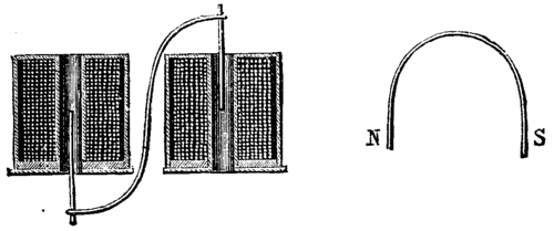
FIG. 2.
The system of needles is suspended from the extremity of a screw, p, which passes into a nut, n, movable between two stationary pieces. On revolving the nut, we cause the screw to rise or lower, along with the entire suspended part, without twisting the thread.
The four bobbins are grouped for tension, and have a total resistance of 30,220 ohms. They contain 16,000 feet of No. 50 copper wire, forming 62,939 revolutions, nearly equally divided between the four bobbins. When a current is passing through the bobbins, the poles of one of the horseshoe magnets are attracted toward the interior of the corresponding bobbins, while those of the other are repelled toward the exterior by the two other bobbins. We thus have a couple which tends to cause the system to revolve around the suspension axis. A mirror, which is fixed upon a vertical piece of aluminum, a, gives, in the usual manner, a reflected image upon a scale, thus allowing the deflections to be read. A compensating magnet, M, is supported by a vertical column fixed to the case, above the needles. This magnet may be placed in the different azimuths by means of a tangential screw, t. The extremities of the bobbin wires are connected with three terminals, T, T1, T, and the instrument may, by a proper arrangement, became differential.
These terminals, as well as the communicating wires, are insulated with ebonite.
Thus arranged, the instrument is capable of making a deflection of one division of 1/50 inch upon a scale placed at a distance of a little more than a yard, with the current produced by one daniell of 10 ohms. This is a degree of sensitiveness that cannot be obtained with any of the astatic instruments known up to the present. By regulating the needles properly, a greater degree of sensitiveness may be attained, but then the duration of the needles' oscillation becomes too great. The sensitiveness of the instrument is sufficiently great to allow it to be used in many cases, even with a moderate duration of oscillation.
In their experiments upon the resistance of glass, the inventors employed an instrument that was not arranged for giving great sensitiveness, and one with which resistances of from 104 to 105 megohms could be measured by the use of a pile of 120 daniells.
The instrument can be given another form. The four bobbins may be arranged symmetrically in the same plane, and the two horseshoe magnets be supported by an S-shaped aluminum bar. The latter traverses the plate that supports the bobbins, in such a way that one of the magnets enters one of the bobbins that correspond to it on one side of the plate, and the other on the other side, as shown in Fig. 2. The bobbins are so connected that, when they are traversed by a current, both magnets are at the same time attracted toward the interior or repelled toward the exterior of the bobbins. Such a form of the instrument has the advantage of being more easily constructed, while the regulation of the magnets with respect to the bore of the bobbins is easier.
The chief advantage of the instrument results from the fact that, owing to the arrangement of the magnets and bobbins, a large portion of the wires of the latter is situated very near the poles of the magnets, and in a position very favorable for electro-magnetic action. The instrument presents no difficulties as regards construction, and costs no more than an ordinary one.
We might even arrange a single horseshoe magnet, or an S-shaped one, horizontally, and employ but a single pair of bobbins, and thus have a non-astatic apparatus based upon the same principle. But in astatic instruments it is better to place the magnets in such a way that the two branches shall be in the same vertical plane.
Were the line that joins the two poles vertical, the system would be perfectly astatic in a uniform field, since each magnet in particular would then be perfectly astatic. A pair of horseshoe magnets may thus be regulated in such a way as to form a perfectly astatic system in a uniform field and to preserve an almost invariable zero, this being something that it is very difficult to obtain with the ordinary arrangement of needles, especially when a compensating magnet is used; for, in such a case, one of the needles becomes more or less magnetized, while the other becomes demagnetized, according to the position of the compensating magnet. - La Lumiere Electrique.
Continue to:
My Books

