Part II. - Hot-Water System, Boilers, Supply Lines, Return Circulation, Steam Connections, And Automatic Regulating Valve
Description
This section is from the book "American Plumbing Practice", by The Engineering Record. Also available from Amazon: Plumbing: A working manual of American plumbing practice.
Part II. - Hot-Water System, Boilers, Supply Lines, Return Circulation, Steam Connections, And Automatic Regulating Valve
To secure an estimated maximum consumption of 500 gallons of hot water an hour for all culinary.
toilet, and domestic purposes two boilers of 5/16-inch galvanized steel with flanged heads were provided. They are about 36 inches in diameter by 6 feet long and are compactly and symmetrically arranged in a narrow space between two massive foundation piers in the cellar adjacent to the cold-water drums and near the post of the engineer, who controls their operation.
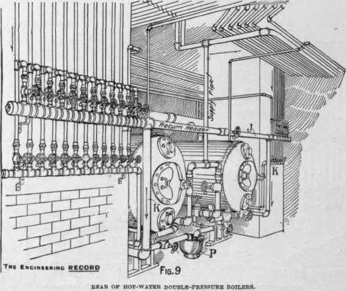
Figure 7 is a view, nearly in elevation, from a photograph, of the front end of the boilers. Figure 9 is a similar view of the rear ends of the boilers after the hot-water pipes and valves were in place, but before the steam connections had been made.
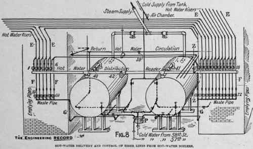
Figure 8 is a general isometric drawing of the boilers and piping as seen from the front.
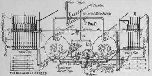
Figure 10 is an isometric diagram of the rear after the connection of the steam pipes.
Figure 11 is a plan from above the boilers.
Figure 12 is a vertical section and elevation at Z Z, Fig. 11.
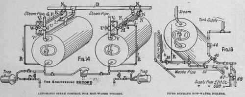
Figure 13 is a diagram of the connections for drip, waste, and return circulation to the underside of one boiler.
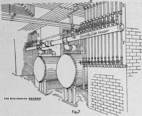
FRONT OF HOT-WATER DOUBLE-PRESSURE BOILERS.
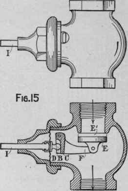
Figure 14 shows the steam connections only, omitting the water pipes shown in the preceding Figures, and Fig. 15 shows the construction and details of the automatic steam regulating valve to control the amount of steam required to maintain the water at a given temperature under varying demands. Tank and street pressure cold water is delivered in 2-inch pipes so connected as to deliver either kind to either boiler without danger of backing into the other one. Water enters the bottoms of the boilers, and being heated by the interior steam coil is delivered from the tops through valved 5-inch pipes which connect with a 5-inch horizontal header which has a valve in the center between the boilers to separate them when they are operated as is usual under different pressures. The header distributes the hot water to 1-inch risers E E, etc., that supply the different groups of fixtures throughout the house, and are each connected at their highest points with ¾-inch return-circulation pipes that enter corresponding 2½-inch headers J at the rear of the boilers. From these headers 2-inch pipes K K connect with the cold-water inlet so that the water that has been cooled in circuit enters with the fresh supply and is continually reheated. All the risers are valved at the headers, and just above are tapped or bled by emptying pipes F F, etc., also valved, and wasted into an open bowl H, contents of which are trapped into a sewer pipe. This system is essentially the same as that for the cold-water drums, Figs. 3, 4, and 5, and similarly provides for the control or emptying of any line by the reversing of its two valves. As with the cold-water distribution drums and in all other places each valve is tagged and its number and corresponding service is printed on a key hung up near by. Some idea of the arrangement and extent of the system is given by the following copy of the hot-water board:
Tank Pressure, Hot Water
1 and 34, boys' bath, Fifth Avenue bath, third floor, and servants' bath Fifty-eight Street, fourth floor.
2 and 35, Mrs. Vanderbilt's bath. 3 and 36, Miss Vanderbilt's bath and Fifty-seventh Street bath, third floor.
4 and 32. west bathrooms, second, third, fourth, and fifth floors.
5 and 33, slopsinks, second, third, fourth, and fifth floors.
6 and 31, Miss Vanderbilt's bath.
Street Pressure, Hot Water
7 and 30, Miss Vanderbilt's bath.
8 and 19, boys' bath and Fifth Avenue bath, third floor.
9 and 20, Mrs. Vanderbilt's bath.
10 and 21, Miss Vanderbilt's bath, Fifty-seventh Street, third floor bath, housekeepers' bath in basement, and library toilet-room.
11 and 22. gentlemen's toilet, men's cellar bathroom, and cellar sink.
12 and 23, ladies' toilet and musicians' toilet-room.
13 and 24, smoking-room toilet, laundry toilet, and cellar sink.
14 and 25, laundry trays.
15 and 26, west bathrooms, second and third floors, and basement slopsink.
16 and 27, kitchen sink, pastry-room, butler's pantry, and two cellar sinks, southwest.
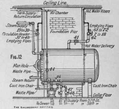
ELEVATION OF HOT-WATER BOILER AT Z Z, Fig. II.
17 and 28, second and third floor slopsinks.
18 and 29, office toilet-room, scullery sink, and basement sinks in waiter's and brush rooms.
37, on circulation distributing pipe of tank pressure boiler.
38, on circulation distributing pipe of street pressure boiler.
39, intermediate valve on distributing pipe connecting tank and street pressure boilers.
40, on tank boiler distribution pipe.
41, on street boiler distribution pipe.
42, intermediate valve on distributing pipe connecting street and tank boilers.
43, tank supply to tank pressure boiler.
44, tank supply to street pressure boiler.
45, street supply to tank pressure boiler.
46, street supply to street pressure boiler.
47, supply to boilers from Fifty-seventh Street.
48, supply to boilers from Fifty-eighth Street.
49, to empty tank pressure boiler.
RETURN-CIRCULATION CONNECTIONS TO HOT-WATER BOILERS.
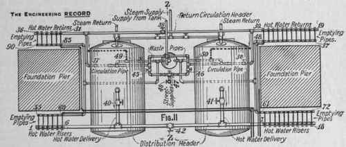
PLAN OF DOUBLE-PRESSURE HOT-WATER BOILERS.
50, to empty street pressure boiler. 51 and 52, supply to steam regulator on tank boiler. 53 and 54, supply to steam regulator on street boiler.
55 to 90 inclusive are emptying valves.
Although it is intended to use one boiler exclusively under street pressure for the lower-floor service, and the other one under tank pressure for the upper-floor service, they are arranged so as to be independent and interchangeable and either or both can be operated from either street or tank supply. Ordinarily, however, the left-hand boiler, Fig. 10, is used for street and the right-hand one is used for tank pressure, and valves 44, 45, 42, and 39, and all emptying and waste valves are closed and all the other water valves are open. Closing valves 46 and 43 and opening 45 and 44 would admit street pressure to the tank boiler and tank pressure to the street boiler, and opening valves 39 and 42 would equalize the pressure between them and connect each boiler with all the hot-water lines, while closing 38, 41, 44, and 46 would cut out the street pressure boiler and allow it to be emptied for cleaning and repairs. By opening valves 39 and 42 in the delivery and return headers all the pipe lines would be served by the tank pressure boiler. Similarly, by closing valves 37, 40, 43, and 45 the tank pressure boiler would be cut out.
The steam pipes supply steam at about 40 pounds pressure to a 60-foot coil of 2-inch brass pipe in each boiler, which is estimated to be capable of heating 300 gallons of water per hour up to 200 degrees. The Kieley traps, drip, and return, etc. are arranged in the usual manner and each boiler is independently supplied through valves T T, Fig. 14. Between valve T and the coil each boiler has a throttle valve U and two by-pass valves V V, so as to permit the steam supply to be automatically proportioned to the amount of cold water heated. To effect this U is closed and V V are opened, admitting steam through regulating valve W, but by reversing valves V V and U the automatic arrangement is cut out and a full head of steam under boiler pressure is constantly freely admitted.
AUTOMATIC SPECIAL STEAM VALVE.
The pipe F receives the hottest water from the top of the boiler and returns it in a continuous stream through pipe N to the bottom of the boiler, thus always maintaining itself at the maximum temperature of the water in the boiler. The variations in this temperature produce small but perceptible changes in the length of the upper horizontal portion of the pipe F (about 4 feet long), and as one end K is relatively fixed the other end that is supported by a loose head M sliding on guide rods G G vibrates longitudinally and actuates the valve stem I. By means of a multiplying device this stem opens and closes the valve W. Screwing up the adjustment nuts N N one revolution each shortens the distance to valve W by an amount equal to the contraction of the pipe F between N and W produced by a fall of temperature of 50 Fahr. and causes a slight motion in the elbow joints L L, which permits the pipe F to move slightly in a longitudinal direction towards Valve W. It may thus be made to operate valve W at any required degree of temperature. The instrument is set to open and close the valve at 1700 and 175° Fahr. respectively.
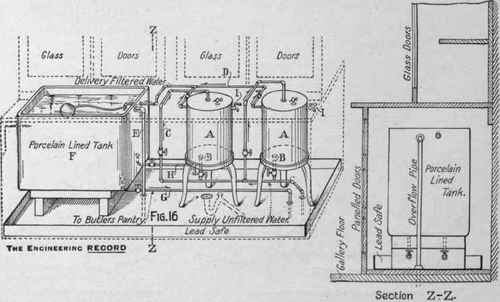
Fig.17.
Fig.18.
Figure 15 shows the details and operation of valve W. Its stem I is fastened to pipe F or head M, Fig. 14, and moves with it so that its expansion by increasing temperature pushes corrugated diaphragm D to the right and makes shoulder B engage the short arm C of the lever L, whose long arm F throws the valve E into its closed position E. This regulator was invented and manufactured by Timothy Kieley, New York City.
Continue to:
My Books

