Stills And Distillation In Practice. Part 5
Description
This section is from the book "Distillation Principles And Processes", by Sydney Young. Also available from Amazon: Distillation Principles And Processes.
Stills And Distillation In Practice. Part 5
Control Of Continuous Stills
To obtain final products of constant composition from continuous stills it is most important to keep a very steady flow of steam and wash to the still and of finished products from the rectifiers.
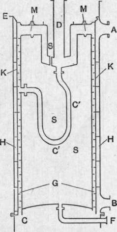
Fig. 116.
Control Of Wash Supply To The Still
The wash flows from a reservoir to the regulator shown on Fig. 117. This works by means of a float A, which rises with the level of wash in the regulator and automatically closes the valve v when a certain level of liquid is reached in the regulator. When the level of the liquid falls, the valve falls open again by its own weight.
Regulation Of Steam Supply To The Still
The steam supply to the still is automatically regulated as the pressure near the base of the rectifying column rises or falls. This is effected by the fig. 117.
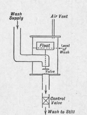
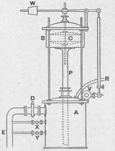
Fig. 118.
Apparatus shown in Fig. 118. The chamber a is filled with water to the level of the outlet cock d.
The pipe r is connected to the base of the rectifying column, so that whatever pressure exists there will be transmitted to the chamber a. Increasing pressure forces the water in a up the pipe p into the chamber B, causing the copper float c to rise and gradually close the steam valve v which controls the steam supply to the boiling column. Decreasing pressure allows water to flow down again into the chamber a, the float to fall and the steam valve to open. The weight w ensures the falling back of the float when the water sinks. Valve d is set so as to adjust the amount of liquid in a. The overflow containing some alcohol from the vapour entering at r is returned by e to the boiling column. The working pressure can be varied by opening x or y.
Regulation Of Rate Of Outflow Of Finished Products From The Rectifying Column
Fig. 119 represents a test glass which will measure the rate of flow of the finished product and enable the flow to be regulated to the desired rate.
The glass vessel f contains a known volume of liquid measured from the point A to the point b.
To test the rate of flow the vessel is emptied to a by opening the cock d. The latter is then closed and the time taken for the liquid to reach B is noted. The process is repeated and the flow is adjusted by the cock c until the desired rate is obtained. The cock d is then partly opened. When the level of liquid in f is steady, this level is noted on the scale e and maintained constant.
Fig. 120 shows an arrangement devised by Barbet and often employed on French stills. The even running of the still is controlled by the means already described.
The vapour leaving the top of the column a passes into the condenser e and is partially condensed. The condensate is returned to the top plate of the column at b. The uncondensed vapour passes on to f, in which it is completely condensed.
Finished spirit is run off from about the third plate from the top of the column, and is cooled in G. The rate of flow is regulated at the test glass p.
The liquid condensed in f flows to the test glass t. The rate of flow at t is fixed in a certain relation to that at P. In practice the flow at p is often fixed at 95 per cent, and the flow at t at 5 per cent of the total flow from both points. Should the condenser e fail to condense enough of the vapour passing through it, owing to irregularity of supply of the cooling water, the excess of un-condensed vapour will be condensed in f, which is always supplied with an excess of cooling water, and will be returned by pipe e, together with the condensate from e, to the top plate of the column.
The liquid drawn off at t is rich in head products. It has been found that the alcohol drawn off from the third plate from the top of the column contains a much smaller proportion of head products than alcohol collected from the top of the column ; and this is not surprising, for the condensers e and f together supply the whole of the condensate for the still. This liquid, which is often equivalent to 6 or 7 times the volume of finished spirit run off through p, flows on to the top plate of the column, where violent ebullition takes place. By this means the head products tend to be driven to the highest point in the still away from the point at which the finished spirit is drawn off. This process is called pasteurisation.
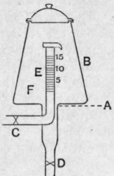
Fig. 119.
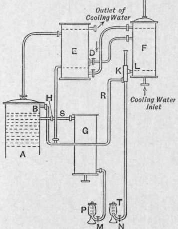
Fig. 120.
By the use of two condensers in series the temperature of the major part of the condensate returned to the top of the column is more easily kept steady, by maintaining a steady temperature in condenser e. The second condenser f ensures the complete condensation of the vapour entering it, but the low temperature of this small part of the condensate does not greatly affect the average temperature of the condensate returned to the column. Were only one condenser used it would be necessary to cool the whole condensate to a lower temperature so as to ensure complete condensation. Any irregularity of supply of condenser water would have a much more harmful effect in upsetting the smooth working of the still.
The specific gravity of the distillate and the temperatures registered at the base and top of the rectifying column are also useful checks in the proper running of the still.
Coffey's Still
Description and method of working.1 - Wash is pumped from a reservoir 3, Fig 121, up the pipe 5, and passes down the zigzag pipe 5 (Col. II.), where it is heated by the ascending vapour; then up the pipe 5 into the highest section of the analyser, column I. It then descends from section to section through the drop pipes, and finally escapes by a trapped pipe 7, at a temperature of about 102° C.
Steam is passed into the analyser by the pipe 4a, and causes the wash to boil, so that by the time it has reached the bottom it is free from alcohol. The ascending vapours pass through the perforations in the plates and bubble through the liquid on them, part of the aqueous vapour being thus condensed, and the descending wash heated.
1 J. A. Nettleton, Manufacture of Spirit. 1893, pp. 133-145.
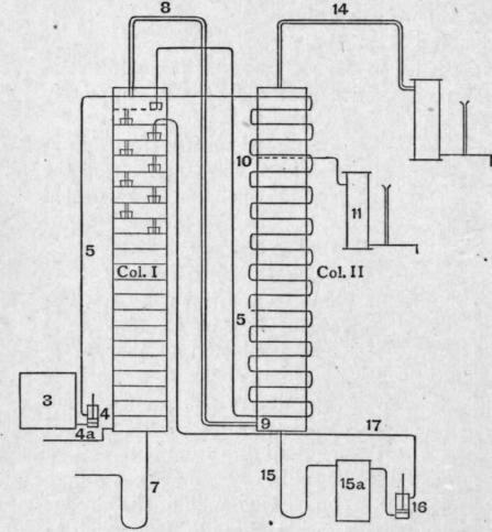
Fig. 121.
On reaching the top of the column the concentrated alcoholic vapour passes through pipe 8 into the base of the rectifier at 9, and then ascends through perforated plates similar to those in the analyser ; the ascending vapour does not, however, meet wash in the rectifier, but spirit formed by partial condensation of the vapour. As the vapour ascends the rectifier it becomes richer in ethyl alcohol, and at a certain level in the rectifier an unperforated copper plate ("the spirit plate ' or Dumb plate) 10 is fixed. In this plate, Fig. 122, a wide pipe or pipes z are fixed which stand up about 1 inch above the plate ; through these pipes the vapour passes. Any liquid produced by the condensation of vapour in the column above this level flows from the spirit plate into the spirit pan which feeds the spirit pipe, from whence it is run to a condenser 11 (Fig. 121). As the level of the liquid rises in the spirit pan it overflows on to the perforated plates below. The flow of the finished spirit is controlled by a cock on the spirit pipe b, Fig. 122. The spirit so produced may contain as much as 94 per cent by weight of alcohol. It may also contain most of the aldehyde and esters and traces of the higher alcohols originally present in the fermented wash. The more volatile by-products may, however, be made to pass together with carbon dioxide away through pipe 14, Fig. 121. They may then be recovered by means of a condenser and gas scrubber. If very pure alcohol is required, the condensate from the top of the rectifying column must not be returned to the analyser, but must be collected and treated separately. The higher alcohols should also be drawn off from the point in the rectifying column at which they tend to accumu-late.But this is seldom done in England. The condensate from the base of the rectifying column flows by pipe 15 to the hot feints receiver 15a, from which it is returned by the pump 16, through pipe 17. to a point near the top of the analyser. The usual way of removing the fusel oil is as follows. When shutting down the still the fusel oil drops with the charge from the plates of the rectifying column into the hot feints receiver. Subsequently water is added to the feints, from which the oil separates on cooling.
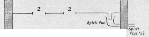
fig. 122.
Continue to:
My Books

