Roofs Generally
Description
This section is from the book "Notes On Building Construction", by Henry Fidler. Also available from Amazon: Notes on building construction.
Roofs Generally
Members In Compression
Generally speaking all rafters, struts, straining beams, etc., are in compression.
Members In Tension
All king posts, queen posts, and rods, and all tie beams or tie rods are in tension.
Members Under Transverse Stress
Principal rafters loaded by purlins or roof-covering along their length, between the points at which they are supported, as in Fig. 464, are subject to transverse stress as well as compression, and tie beams carrying ceiling joists are also subject to transverse stress.
Timber Roofs
Figs. 461 to 465 give skeleton diagrams of ordinary roof trusses (see also Plate IV.)
Fig. 461.
Fig. 462.
Couple Roof (Fig. 461) And Tied Couple Roof (Fig. 462)
The rafters are in compression, and the tie in Fig. 462 is in tension.

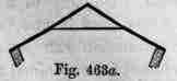
Collar Beam Roof, - In this, so long as the walls stand firm (Fig. 463), the beam is a strut and supports the rafters, but if the walls are weak and give way, the beam becomes a tie as shown in Fig. 463a.
Fig. 464.
Fig. 465.
King-Post Boo/And Queen-Post Roof (Figs. 464, 465)
Nothing need be said about these, except that in Fig. 464 the principal rafters being loaded by the roof-covering between their points of support are subject to transverse stress, as well as the compression upon them, and the tie beam being loaded by the ceiling is also subject to transverse stress as well as tension.
When the purlins are only at the points at which the principal rafter is supported, as in Fig. 465, it is not subject to transverse stress, nor is the tie beam, where there is no ceiling.
Other Framed Structures. Trussed Beams
The diagrams, F'igs. 466, 467, show by thick lines the members in compression, and in thin lines the members in tension in trussed beams (see Parts I. and IV.)
Fig. 466.
Fig. 467.
These will be the same in nature though not in amount, whether the load be distributed along the upper surface or concentrated at points.
When the load is distributed between the points where the bracing joins the upper beam, the latter is of course subject to transverse stress as well as to compression.
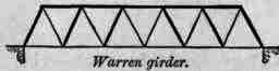
Fig. 468.
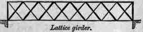
Fig. 469.
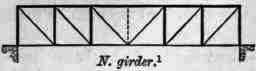
Fig. 470.

Fig. 471.
Braced Girders
Figs. 468 to 471 are common forms of braced girders, and they show by thick lines the members in compression, and by thin lines the members in tension, when the girders are carrying loads uniformly distributed along the lower flange or at the points where the braces join that flange.
The stresses will be similar in character when the load is on the upper flange, but in Fig. 470 an additional bar will have to be introduced as dotted, and it will be in compression.
Such girders are frequently suspended between their abutments from the ends of their upper flanges ; in such a case the construction at the ends of the girder is slightly different, but the nature of the stresses is practically the same as shown in the Figures.
F. "In the case of a concentrated or uniform load upon any part of a beam supported at both ends to ascertain the proportion of the load transmitted to each point of support."
Concentrated Load In Centre Of Beam
If a concentrated weight W be placed upon the centre of a beam supported at the ends, then half the weight is borne at each end. Thus in Fig. 472 half the weight W is borne on each abutment.
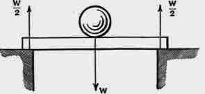
Fig. 472.
Load Uniformly Distributed Over Whole Length Of Beam
If a load, 8 w etc., Fig. 473, is uniformly distributed over a beam, then again half the load (in this case 4 w) is borne by each abutment.

Fig. 473.
1 Sometimes called Whipple-Murphy girder.
Weight Of The Beam Itself
The weight of the beam itself is like a uniform load, and half that weight is supported by each abutment.
Load At Any Point Of Beam
The proportion of the load borne by each support may, avoiding formulas, be found by the following rule.
Rule
If a load is placed anywhere on a beam, supported at both ends, then the proportion of the load borne by either support is equal to the load, multiplied by the distance from its centre of gravity to the other support, and divided by the length of the beam between the supports.
Concentrated Load
Thus in Fig. 474 the load W is 400 lbs., and it is distant 5' 0" from A and 10' 0" from B.

Fig. 474.
The proportion of W borne at A is equal to
W X distance DB |
Length AB |
i.e. =
400 lbs. x 10 feet |
15 feet |
= 266 2/3 lbs.
The proportion of W borne at B is equal to
W X distance DA |
Length AB |
i.e. =
400 lbs. x 5 feet |
15 feet |
= 133 1/3 lbs
Reaction
The proportion of the load borne by each support is called the reaction at that support. In Fig. 474 the reaction at A is shown as R = 10 1/15 400. Reaction at B, R = 5/15 x 400.
Load Uniformly Distributed Over Central Part Of The Length Of A Beam
In this case the load may be considered as acting through its centre of gravity, and then its reactions are found as in the case of a concentrated load at the centre.
Thus if the load were uniformly spread over an equal distance on each side of the centre of the beam as in Fig. 475, then half the load is borne by each support.
Similarly when the uniform load is made up of a number of weights 4 w, then each support takes 2 w.

Fig. 475.
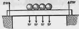
Fig. 476.
Load uniformly distributed over any Part of the Length of a Beam.
In this case the load is equivalent to a single concentrated load at the centre of gravity of the distributed load. Thus in Fig. 477 the weight of the tank which is distributed over E F may be taken as acting at D through its centre of gravity.
The reactions are then just the same as in the case illustrated in Fig. 474.
Again when the distributed load is made up of separate weights as in Fig. 478, they may be considered as acting through their common centre of gravity, and the reactions are again the same as shown in the Fig. 474.
Any Number Of Concentrated Loads On A Beam
When the loads are unequal, and placed unsymmetrically, the reaction of each at each support is found in turn. The total reaction at either support will be the sum of the reactions produced by each weight at that support.

Fig. 477.
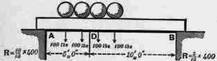
Fig. 478.
Take a simple case, with only two unequal weights placed unsymmetri-cally, as shown in Fig.

Fig. 479.
Applying the rule given above for a single weight not in the centre of the beam, we have -
N.B. - The consideration of bending moments, moments of resistance, shearing stresses, etc., and calculations for strength, even for the simplest learns, does not form a part of this Course but is entered upon in Part IV.
at A | atB | |||||
Reaction produced by W1 | 10/20W1=10/20. 300 | = | 150 | 10/20W1=10/20.300 | = | 150 |
" " W2 | 15/20 W2 = 15/20.100 | = | 75 | 5/20W2 = 5/20.100 | = | 25 |
Total reaction produced by W1 + W2, i.e. by 300 + 100 lbs. | 225 lbs | 175 lbs. | ||||
Continue to:
My Books

