Radiators. Construction Of Radiators
Description
This section is from the book "A Treatise On Architecture And Building Construction Vol4: Plumbing And Gas-Fitting, Heating And Ventilation, Painting And Decorating, Estimating And Calculating Quantities", by The Colliery Engineer Co. Also available from Amazon: A Treatise On Architecture And Building Construction.
Radiators. Construction Of Radiators
74. Radiators which are made of ordinary steam pipes and fittings, as shown in Figs. 27 and 28, are usually called colls. Coils are also made of continuous pipes, which are bent and curved to a great variety of shapes.
75. The continuous flat coil, Fig. 27, is made of straight pipes connected by return bends. The circulation of the fluid through it is direct and certain, and it is regarded as the most efficient form of radiator in common use.

Fig. 27.
76. A miter coil is shown in Fig. 28, the pipes being connected between two manifolds a and b. The steam moves .forward simultaneously through all the pipes; its velocity, therefore, will be one-sixth of the rate in a single pipe, as in Fig. 27. The circulation is likely to be uneven, because the fluid entering at g will naturally flow by momentum to the end of the manifold, and will enter the pipe e in greater quantity than into the pipe f. The path through e c is shorter than through f d, and, the friction being less, the main part of the current will go that way.
It will be noted that all the horizontal pipes are connected to the manifold a by means of elbows and vertical pipes. This must always be done, so as to permit the several pipes to expand independently, as their differing temperatures may require. The vertical pipes will bend or yield sufficiently to accommodate the difference in expansion.

Fig. 28.
If a coil is made by connecting two manifolds, parallel to each other, it will be difficult to keep it steam-tight. The pipes will expand unequally and will crack or break some of the connections.
When several flat coils are grouped together, the construction is called a box coil.
77. The size of pipe used for constructing coils depends mainly upon the pressure of steam to be employed, length of the coil, and the force of the circulation through it. The sizes in common use are from 1 inch to 2 inches.
Pipe coils must be arranged so all of the water which is condensed within them may flow easily towards their outlets.
78. Fig. 29 shows a tube called the Nason tube. It connects to the radiator base by a single screw joint, and is divided into two passages by means of a sheet-iron plate a which extends nearly to the top of the tube, as shown.

Fig. 29.

Fig. 30.

The steam rises on one side, passes over the end of the plate, and descends on the opposite side of the tube. Each tube thus forms a complete loop, or circuit.
79. Fig. 30 shows the Bundy loop, in longitudinal section at A and cross-section at B. This, also, is screwed into a cast-iron radiator base of suitable shape, and the steam moves up one branch of the tube and down the other.
80. The Detroit loop is shown in Fig. 31. Each loop is complete in itself, and requires no base or supply chamber. They are connected together, in any number desired, by means of nipples a and c. When the connection at the top is not desired, the loops are bound together by a bolt which passes through the space between them, shown in the end view.
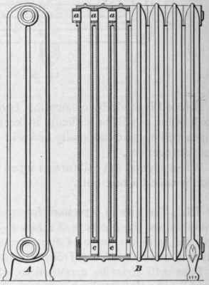
Fig. 31.
The construction of this class of loops is often varied so that they comprise three or even four parallel tubes. They are also modified so as to form flue radiators.
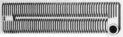
Fig. 32.
81. Fig. 32 shows an extended surface loop which is especially designed for indirect heating. These loops, or sections, are coupled together by nipples, as illustrated at a and c in Fig. 31.
Another variety which is in extensive use for indirect heating is shown in Fig. 33. This is called a pin radiator, because the extensions of the heating surface are made in the shape of small conical pins. The sections may be coupled at both top and bottom, as shown.
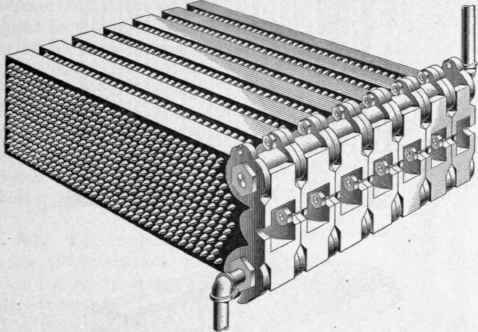
Fig. 33.
82. Radiators of the kind shown in Fig. 31 should have supports at. short distances apart, particularly when the loops are not connected together on top. If the radiator is over 3 feet long, the middle loop should be provided with feet, and, in the case of very long and low radiators, the supports should not be more than 30 inches apart. Every foot should bear firmly on the floor, to prevent sagging of the radiator and consequent straining or rupture of the joints, or cracking of the castings.

Fig. 34.
83. The radiators which are commonly used for heating air on a large scale, where forced draft is employed, are usually constructed as shown in Fig. 34. The tubes are of 1-inch steel or wrought-iron pipe, and are connected at the top by cross pipes, instead of return bends, thus preventing all distortion by unequal expansion.
The tubes are staggered, so that those in one row stand opposite the spaces between the tubes in the preceding row. By this means, all parts of the air-current (which passes through horizontally) are brought into contact with the tubes and are thoroughly heated.
The base sections, or headers, are coupled together at one end by flanged joints. The group of base sections may be divided into two or more parts, each of which may have an independent supply and return pipe. Thus, the whole heater may be used, or only a part of it, as desired. The sides of the sections are corrugated so that they interlock and leave no open spaces between them. The farther end of each section rests upon a roller e, so that they can expand and contract freely without straining. The course of steam through the heater is shown by arrows.
84. The ordinary varieties of vertical-tube radiators may easily be adapted to direct-indirect heating. The mode of applying a direct radiator of the Nason or Bundy type to that purpose is shown in Fig. 35. The base of the radiator is enclosed by plates a, so that the fresh air, which comes in through the flue b, is compelled to pass upwards and between the hot tubes before it can escape into the room.

Fig. 35.
Flue radiators may be applied in a similar manner by enclosing the base and compelling the fresh air to pass up the flues.
Continue to:
My Books

