Application Of Graphic Statics To Trusses With Vertical Loads. Continued
Description
This section is from the book "Building Construction And Superintendence", by F. E. Kidder. Also available from Amazon: Building Construction And Superintendence.
Application Of Graphic Statics To Trusses With Vertical Loads. Continued
130. - Method Of Lettering The Truss Diagram
The method of lettering the truss and stress diagrams used in the following examples is after what is known as "Bow's Notation," and aids the student very materially in tracing the stresses in the stress diagram, and in avoiding errors, besides affording a means for designating the various lines and a ready comparison of the stress diagram with the truss diagram.
The essential feature of this notation is that in the truss diagram a letter is given to the Spaces between the lines or forces, and each line or force is designated by the letters on each side of it. Thus in Fig. 275, the entire space cut off by the supporting force P1 the rafter and the load line at joint 2 is designated by A, the space between the load lines at 2 and 3 and bounded by the rafter is designated by B, and the entire space beneath the truss and between P1 and P2, by O. The force P1, being between spaces O and A, may be designated as O A. The load at 2, represented by the arrow, is between A and B, and hence is designated as AB. The lower half of the rafter is designated as AE, and the left half of the tie beam as EO. .
In the stress diagram, the same letters come at the ends of the corresponding lines, so that the line ae in the stress diagram shows the magnitude of the stress in AE. Capital Letters are always used on the truss diagram and small letters on the stress diagram, hence in the description capital letters always refer to the former and small letters to the latter. It does not make any difference what letters are used but the author finds it convenient to use the first letters, as A B C, etc., to denote the spaces above the truss, and between the forces, the first left hand space being always designated as A.

Fig. 275.
Whenever it is found that the stress diagram cannot be lettered to correspond with the truss diagram, then we may be sure that some mistake has been made either in the lettering of the truss diagram or in drawing the stress diagram.
Problem I, Fig. 275. - As the first problem in drawing the stress diagram for a truss, we will take a simple king rod truss, with three external loads. The truss diagram should be carefully drawn to a scale of 1/4-inch or 1/8-inch, to the foot, as most convenient, and lettered as in Fig. 275. The stress diagram should be drawn on the same sheet of paper, and as close to the truss diagram as practicable without encroaching upon it. In this first problem a separate stress diagram for each joint is shown in order to more clearly explain the principle, but in practice one diagram is drawn to show the stresses for the entire truss.
In drawing the stress diagram, the first line to be drawn (except in a few special cases) is a vertical line representing one of the supporting forces, and for trusses supported at each end it is more convenient to start with the left hand support P1, and to take the stresses acting at that point (joint 1) in order from left to right. In this instance P1 = 3,000 lbs., and a convenient scale will be 2,000 lbs. to the inch. (Note. - For measuring the stress diagram an engineer's scale, graduated to 20ths, 30ths, 40ths, 50ths, etc., of an inch should be used.) The stress diagrams in Fig. 275 were drawn to a scale of 20ths (2,000 lbs. = 1 inch or 100 lbs. = 1/20 of an inch) and reduced by the photo-engraving process to 2/3ds the original size, so that in the engraving the scale is about 3,000 lbs. to the inch. The scale to be used in any particular case will depend upon the amount of the loads. If P1 is less than 8,000 lbs., a scale of 2,000 lbs. to the inch is best. When P1 is between 8,000 and 18,006 lbs., a scale of 3,000 lbs. to an inch is more convenient. As a rule the scale should be such that no line in the stress diagram will exceed 14 inches in length.
We will commence our stress diagram, therefore, by drawing a vertical line oa (Diagram A) = 3,000 lbs. or 1 1/2 inches in length.
As the supporting force acts upwards, the arrow head should be at the top, and the line must be lettered oa. The letter designating the space to the right of P1, being O, o must be at the bottom of the line and a, at the top. The next force acting at joint 1, going around as the hands of a clock, is the stress in AE, and as the arrows must always point from each other, the line in the stress diagram representing AE must start from a. The fact that we already have the letter a, also shows that ae must start from a, then, from a draw a line of indefinite length parallel with the line AE. The next force acting on the joint is the stress in E O, which, with oa and ae must form a closed triangle in order to preserve equilibrium. Therefore, the stress line for EO must pass through o, and to obtain the point e, draw a line through o, parallel with OE, until it intersects the slanting line drawn through a. The point of intersec-section of these two lines gives the point e, and the stress diagram for joint 1, is the triangle oae. The arrow head on eo must point towards o, to preserve the rotation. If now we notice the direction of the arrow heads we see that the head on ae points towards joint I, and that on eo from joint 1, consequently the former denotes compression and the latter tension.
Stress Polygon for Joint 2. - At joint 2 we have two known forces - the stress ea and the load, and two unknown forces. To show the stress polygon for joint 2, separately, draw a line ea parallel to AE, and of the same length as in diagram A (Fig. 275), and from a, draw a vertical line equal to 2,000 lbs. - the amount of the load. The arrow head on ea will now point in the opposite direction from that in diagram A (see § 125), or towards a, and the polygon begins with the point e. To obtain bf and fe, from b and e draw lines parallel to BF and FE, respectively, and letter the point of intersection f. Polygon B then represents in direction and magnitude all of the forces acting at joint 2.
As the stresses for corresponding members on each side of the stress must be alike, diagram A and B give the stresses for all of the members of the truss except the centre rod, FG. To obtain the stress in this member we may draw the diagram for either joint 3 or joint 5, but that for joint 3 is the simpler. At joint 3 we have the known forces fb and be (the load) and the unknown stresses in CG and GF, which we obtain by drawing lines through c and f (diagram C), parallel respectively to CG and FG. The arrow head on fb must point in the opposite direction from that in diagram B, or towards b, and the heads on the other lines must point from each other as shown. We see that the head on gf points from the joint, indicating tension. By scaling the lines in the three diagrams A, B and C, with the scale to which oe was drawn, we obtain the magnitude of the stresses, or 4,440 lbs. for ae, 3,000 lbs. for eo, 1,420 lbs. for ef, 2.820 lbs. for bf and 2,000 lbs. for fg.
As the truss rafters are drawn at an angle of 45 degrees, it is evident that oe must be equal to oa, and that
Stress Diagrams for Entire Truss. - In practice it is much easier to show all of the stresses in one diagram, as at D, which contains all of the lines shown in diagrams A, B, and C, and is drawn in the same order as given above for the separate diagrams. In the single diagram, however, it is not practical to show the arrow heads, as each line would require two heads, and they become confusing in the engravings. The direction in which the forces act, however, must be kept in mind, and a few of the heads may be indicated in pencil, if necessary.
In diagram D, if having drawn the stresses at joint 3, we wish to draw those for joint 4, we start with the line gc, already drawn, which must act towards c, lay off the distance cd = 2000 lbs., and from d, draw a line parallel to DH, and from g, a line parallel to GH, the two lines intersecting at h, and we have the completed diagram for the entire truss, which must be symmetrical about the line eo. As DH and FE are parallel, also AE and GH, dh and gh lie over fe and ae, and the points h and e coincide. This often happens in stress diagrams, but each line should be considered as a separate line for its entire length, and properly lettered, as the lettering assists very effectually in avoiding mistakes.
Problem 2. Fig. 276. In this figure, we have shown the truss diagram for the truss shown in Fig. 249, and for which the roof loads are computed on page 234, example 5, truss 3. This truss in addition to the roof loads also has three ceiling loads which must be considered. When the ceiling loads are directly supported by vertical rods these loads may be considered as applied at the top of the truss and added to the roof loads, without affecting any of the stresses except those in the rods supporting the respective ceiling loads. As the stress diagram is a little simpler, when the loads are applied at the top only, the author generally follows this method of adding the ceiling loads to the roof loads directly above, and drawing the stress diagram as if there were no ceiling loads. When this is done, however, the ceiling load must be added to the stress given by the stress diagram, to obtain the true stress in the rods.
In the truss in question there will be no stress in the outer rods from the roof loads, and the tension in them will be just the amount of the ceiling loads, or 1800 lbs. In the center rod the real stress will be that shown by the stress diagram, or 7,200 lbs. plus the ceiling load of 1,950 lbs.
That the ceiling load may not be overlooked in computing the total stress, it is well to put the loads beside the member in the truss diagram, preceded by the sign +.
It is also a good plan to put on the sheet the loads per sq. ft. for which the truss is designed, and also the spacing of the trusses or if the trusses are not spaced evenly, the length of roof which the truss supports. All of the data relating to the strength of the truss will then be on one sheet.
In the truss diagram, members which do not enter into the stress diagram should be shown by dotted lines, and the diagram lettered as though these members did not exist. Thus in the truss diagrams, Fig. 276, the letter D refers to the entire triangle 1-2-5.

Fig. 276.
The stress diagram is drawn in precisely the same way as the diagram in Problem 1, commencing by drawing the line oa = to P1, 11,650 lbs. at a scale* of, say, 3,000 or 4,000 lbs. to the inch. From a, draw a line parallel to AD, and from o, a horizontal line, the two intersecting at d. At joint 2 we have the stress da, and measure downwards from a, the load AB = 7,550 lbs. giving the point b. From b, draw a line parallel to BE and from d, the point of beginning, a line parallel to ED, and lines intersecting at e, then the lines da, ab, be, and ed, form the stress polygon for joint 2. For the stress polygon at joint 3, we have eb, and measure down from b, the load of 8,200 lbs. giving the point c. From c. draw a line parallel to CF, and from e, the point of beginning, a line parallel to FE, the two intersecting at f. We now have the stresses for all of the members of the truss, the magnitude of the stresses being indicated by figures on the stress diagram.
*In the engraving the scale is about 6,000 lbs. to the inch.
It is not worth while to figure the loads or stresses of a roof truss closer than 50 lbs., as the truss cannot be proportioned with a greater degree of accuracy.
Checking the Stress Diagram. The accuracy of the stress diagram in the case of triangular or Howe trusses can readily be checked by a few simple computations, which it is often well to make. As the lines of the triangle dao are parallel respectively to those of the triangle 1-3-5, the triangles must be similar, consequently,
1 - 3 x ao
1 - 3: 3 - 5:: da : ao, or da =
3 - 5
1 - 5 x ao and 1 - 5: 3 - 5:: do : ao, or do = and ao = 11,050 lbs.
3 - 5
In this case, 1 - 5 = 16' 8" = 200"; 3 - 5 = 170": 1 - 3 =
262.5 x 11,650
Therefore, da = ----------------- = 17,989 lbs.,
200 x 11,650 and do = ----------------- = 13,706 lbs.
The other stresses can also be checked in a similar manner, but if the principal lines of the stress diagram scale within 100 lbs. of their computed values, then the rest of the diagram will be likely to be fully as accurate.
Data for easily checking the stresses in end panels of all triangular and Howe Trusses, supported at each end, and having the main tie horizontal.
In the above examples we used the full half span, and the full rise to obtain the stress in do, but we would have obtained the same result by using any two numbers having the same ratio to each other, as 100 and 85, or 20:17, or in other words, it is the proportion which the sides bear to each other, or the inclination of the strut which determines the stresses, and not the actual dimensions of the panel.
For trusses supported at the ends and with the main tie horizontal, the stresses in the end panel are governed solely by the supporting force, and the angle of the strut, hence for any given angle the stresses may be found by multiplying the supporting force by the factors for that angle.
Table XII gives the factors for a number of angles, expressed in degrees, and also by the rise in 12 ins. These factors may be used for unsymmetrical, as well as symmetrical trusses, and also for trusses unsymmetrically loaded, if the supporting forces are correctly computed, but they do not apply to trusses in which the main tie is inclined. They also give the stress for the end panel only. For angles not given in the table, it will be necessary to check the stresses by proportion as in the foregoing example.
Table XII. - Factors For Computing Stresses In End Panels Of Trusses With Horizontal Tie Beam
Inclination of strut. | Rise in 12 Ins. | Factor for strut. | Factor for tie beam. | |||
60° | 20.78 | Ins. | 1.155 | .5773 | ||
51° | - | 20' | 15 | " | 1.28 | .8 |
49° | - | 24' | 14 | " | 1,317 | .857 |
47° | - | 17' | 13 | " | 1.36 | .923 |
45° | 12 | " | 1.414 | 1. | ||
42° | - | 30' | 11 | " | 1.48 | 1.091 |
41° | - | 11' | 10 1/2 | " | 1.518 | 1.143 |
39° | - | 48' | 10 | " | 1.562 | 1.2 |
36° | - | 52' | 9 | " | 1.666 | 1.334 |
33° | - | 41' | 8 | " | 1.803 | 1.50 |
30° | 6.93 | " | 2. | 1.732 | ||
26° | - | 34' | 6 | " | 2.236 | 2. |
22° | - | 30' | 4.97 | " | 2.611 | 2.414 |
Problem 3. Fig. 277. For this problem we will take the same truss as in Problem 2, and show how the stress diagram is drawn when the ceiling loads are not combined with the roof loads. In this case the outer rods will be represented in the stress diagram, and must be shown in the truss diagram by full lines, and each triangular space must have a separate letter. In order to facilitate a comparison between the diagrams in Figs. 276 and 277, the same letters have been retained, and the letters D', R and S, added in Fig. 277.
As the total loads is the same in each problem the supporting forces must be alike.
At joint 1, we have precisely the same forces acting as in Fig. 276, consequently the triangle of forces for this joint will be the same in both problems, or in Fig. 277, we start with oa = 11,650 lbs. and draw ad and od, precisely as in Fig. 276, and if drawn to the same scale, the corresponding lines must be of the same length. At joint 3, Fig. 277, we now know the stress in AD and the load AB, but we have three forces that we do not know, viz., the stress in BE, ED' and D'D, and when there are three unknown forces we cannot draw the stress diagram for that joint until one of the forces has been found or assumed. At joint 2, we have but two unknown forces, viz., the stress in DD' and D'R, therefore, we can draw the stresses for this joint. In drawing the stress diagram for any joint, always commence with the known force, furtherest around to the right, which in this case is the load RO. Now, as we already have the point o, we know that one end of ro must be at o, and as the force acts down, the other end must be above, therefore to find the point r, we measure upwards from o, 1,800 lbs., and r is the beginning point of the stress polygon for joint 2. We now have ro, od, and from d, draw a line parallel to DD' and from r, the point of beginning, a line parallel to D'R, the two intersecting at d'. As we now have the stress d'd, we can proceed to complete the stress diagram for joint 3. The first known force at joint 3 is d'd, acting down, or away from the joint, next, da, then measure down from a, 5,750 lbs., which gives the point b, and the point e is obtained by drawing lines through b and d' parallel respectively to BE and ED'. Next, complete the stress polygon for joint 4. Here we have the lines eb and measure down from b, the load of 6,250 lbs., which gives the point c. Through c and e draw lines parallel respectively to CF and FE which will intersect at f. As we now have the stress in the center rod and all of the members to the left, it is not necessary to carry the diagram further, but to show that the completed diagram would be symmetrical, we will carry it one step farther, by completing the stress diagram for joint 5. The first known force at this joint, around to the right, is the load of 1,950 lbs., which termintes at r, and as it acts down, s must be above it, a distance of 1,950 lbs. We then have sr, rd', d'e, ef, and draw gs and fg. Now if the diagram has been accurately drawn a horizontal line drawn halfway between the points s and r will pass through the intersection of eb and cf and bisect fe, and if the stress diagram is carried out one step farther so as to show the forces acting at joint 6, the diagram will be found to be symmetrical about this center line.

Fig. 277.
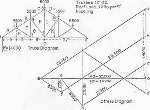
Fig. 278.
If now we compare the stress diagram in Figs. 276 and 277, we will see that the slanting and horizontal lines are of the same length in both diagrams, and that fe in Fig. 277 is just 1,950 lbs. longer than in. Fig. 276, which is the amount of the ceiling load sustained by the rod. The length of dd' is the same as ro, or the stress is just the amount of the ceiling load. The same result is obtained, therefore, by either method.
Problem 4. Fig. 278. Six panel queen truss with roof loads only. Commence the stress diagram by drawing the line oa = P1 = 14,000 lbs., then draw ae and oe as in the preceding problems. Complete the polygon for the different joints in the order in which they are numbered. The rise of the rafter is 2' in 3' or 8" to the foot, and by Table XII. eo must equal 14,000 x 1 1/2 or 21,000 lbs.

Fig. 279.
Problem 5, Fig. 279. This represents the truss shown by Fig. 253 and for which the roof loads are computed in example 6, page 234. It is assumed that the truss also supports a ceiling for which the joint loads have been computed on a basis of 20 lbs. per sq. ft. In this problem the ceiling loads are first added to the roof loads directly above, and also added to the stresses for the rods given by the stress diagram, as explained in Problem 2. The stress diagram is drawn precisely in the same manner as that for problem 4, taking the joints in the order in which they are numbered, fo should equal
19-335x 8.66 or 33488 lbs., and if it scales within 100 lbs of this value, it will show a good degree of accuracy. The stress diagram should be drawn to a scale of 4,000 lbs. to the inch.
Problem 6, Fig. 280. This truss has the same span and rise as that shown by Figs. 253 and 279, and is figured for the same roof and ceiling loads, but in this truss the struts or braces are arranged to come under the purlins so as to avoid a transverse strain in the ratter and the rods are inclined. As the total roof and ceiling areas supported by the truss are the same as those supported by the truss Fig. 279, the supporting forces should have the same value (the difference of 35 lbs. is due to the fact that the joint loads have been taken slightly in excess of the actual computations). As the rods in this truss are inclined, we cannot add the ceiling loads to the roof loads but must show them separately in the stress diagram, as in Prob. 3. When the ceiling loads are shown separately in the stress diagram the spaces between the ceiling loads must each have a special letter.
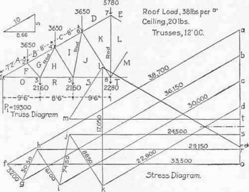
Fig. 280.
Commence the stress diagram as in all of the preceding problems, by drawing a vertical line oa equal to P1 at a scale of say 4,000 lbs. to the inch, and from a and o draw lines parallel respectively, to AF and FO intersecting at f. Then complete the stress polygon for joint 2. Here we have fa, measure down ab = 3,650 lbs. and from b and f draw lines parallel to BG and GF, intersecting at g. For the stress polygon for joint 3, we must start with the load RO, the point r being obtained by measuring upwards from o, 2,160 lbs. We then have ro, of and fg, and from r and g draw lines parallel to HR and GH, intersecting at h. For joint 4 the stress polygon is hg, gb, be, ci and ih. Continue in the same manner for joints 5, 6 and 7. For joint 8 we start by measuring upwards from s, 2,280 lbs. which gives the joint t. We then have ts, sj, jk and kl, and from 1 and t draw lines parallel respectively to LM and MT intersecting at m. If the diagram has been accurately drawn the point m will be directly above j, and a horizontal line bisecting ts will pass through the intersection of el and kd, and bisect Ik.
As the inclination of the rafter and the amount of supporting force is the same as in Prob. 5, the stress triangle for joint 1 should be the same in the two stress diagrams (if drawn to the same scale) or the stress in AF and FO should be the same in both cases.*
Problem 7, Fig. 281. For this problem we have the case of an unsymmetrical truss, symmetrically loaded. The outline of the truss is similar to that of the truss on the right, Fig. 123. The loads are approximately what they would be for a spacing of 14' 6" center to center of trusses.
As the loads are applied at equal distances from the supports, the reactions must be equal and each equal to one-half of the total load, or 10,500 lbs.
The stress diagram is drawn in precisely the same manner as those for the preceding examples, commencing with the supporting force P1 = oa = 10,500 lbs. The stresses should be drawn in the order in which the joints are numbered. For the stress polygon at joint 5, we have the lines og and gh, and draw hi, intersecting og prolonged. For joint 6, we now have ih, hc, cd = 7,000 lbs. and a line drawn from d parallel to the rafter must pass through the point i, to close the polygon. If a line from d parallel to DI, does not pass through i, it shows that either the stress diagram or the truss diagram has not been drawn with sufficient accuracy. As a matter of fact, a very slight inaccuracy in the measurements of the truss diagram, or in drawing the lines of the stress diagram perfectly parallel with those of the truss diagram will cause the line through d to pass to one side of the point i. It is well to notice in this problem that the stresses at the right end of the truss are much greater than those at the left, due to the lesser height on that side. As the angle of the long rafter is 22 1/2 degrees, the length of the line oi should equal 10,500 x 2.414 (Table XII.) = 25,347, which very closely corresponds with the scale.
*In order to show the stress diagram in Fig. 280 more clearly, it was drawn to a larger scale than that in Fig. 279, but the result is the same. The stresses in the other members of the truss, however, vary considerably, because of the difference in the inclination of the web members. It should be noticed that the stress in the rods GH and IJ is considerably greater in Fig. 280 than in Fig. 279.

Fig. 281.
Problem 8, Fig. 282. The truss diagram is that of the truss shown by Fig. 256, the distance a, Fig. 256 is 9' 9", b 13' 4", and c, 12 ft. As the trusses are spaced 15 ft. on centers, the roof area supported at joint 2 = 9' 9" x 15', = 146 1/4 sq. ft. At joint 3, the roof area supported = 13-1/3 x 15 = 200 sq. ft., and the ceiling area supported at joint 7 = 12' x 15' = 180 sq. ft. Multiplying these areas by the respective loads per sq. ft., we have in round numbers, the loads indicated on the truss diagram.
In Fig. 256, counter braces are shown in the center panel, but as explained in § 7, there will be no stress in these braces under a symmetrical load; they cannot be shown in the stress diagram and should therefore be omitted from the truss diagram. In this example we have added the ceiling loads to the roof .loads directly above, so that the stress diagram will be drawn as though there were no ceiling loads. To draw the stress diagram commence by drawing the vertical line oa, of a length equal to P1, or 18,500 lbs. at a scale of 4,000 lbs. to the inch (the scale of the engraving is 7,500 lbs. to the inch) and from a and o, draw lines parallel respectively to AE and EO, intersecting at e. As the supporting force acts upwards, the arrow head on oa will be at a, on ae at e and on eo at o, showing that ae is in compression, and eo in tension.

Fig. 282.
Next, complete the diagram for joint 2, the first known force at this joint is the stress in the rafter, represented by the line ea, which now acts towards a, next the load of 6,300 lbs., which acts down, and which when measured off to the scale gives the point b, then from b and e draw lines parallel respectively to BF and FE, intersecting at f. The force bf acts towards f, and fe towards e, showing that both members are in compression (as the forces act towards the joint). Next, complete the diagram for joint 3. The first known force at this joint is fb, which now acts towards b, next the load of 12,200 lbs. which takes us to the point o, where we also put the letter c. As the top chord CG is horizontal, and the point c coincides with o, the stress line for C G will lie over or coincide with that for EO, and its length will be obtained by drawing a line from f parallel to GF, until it intersects eo at g. Then eg will be the stress line for CG, with the arrow head pointing towards g and denoting compression. If now we trace the polygon of forces for joint 7, we find that we have oe, ef, fg and that go must close the polygon or that the stress in GO, is just equal to that in CG.
Scaling the stress diagram, we obtain the stress indicated. We should not forget that the true stress in the rod FG is that indicated by the line fg (3250) + the ceiling load of 3,600 lbs. or 6,850 lbs.
Problem 9, Fig. 283. Stress diagram for a truss like that shown by Fig. 19, with dimensions as shown on the truss diagram Fig. 283. It is assumed that the portion of the attic included within the heavy black line is to be finished and used for ordinary purposes. The roof load at 46 lbs. per sq. ft., will allow for a slate roof. With the trusses spaced 12 ft. on centers, the roof loads will be about as indicated by the upper set of figures. Included in the roof loads at joints 2, 4 and 5, is the weight of the plastered ceiling, the stress on the center rod being 1,010 lbs. The load at point 8 is estimated as follows:
42 | sq. ft. of floor, at 20 lbs., equals...................... | 840 |
42 | sq. ft. of floor, at 60 lbs, equals........................ | 2,520 |
60 | sq. ft. of studding, lath and plaster, at 15 lbs., equals...... | 900 |
Total...................................... | 4,260 | |
Load at 3 = 10 1/2 x 12' x 60 = 7,560 lbs. | ||
The stress diagram for joints 1 and 2 is drawn precisely as in Fig. 281, but in this truss we must complete the stress diagram for joint 3 before we can draw that for joint 4.
At joint 3 the first known force is the stress in OE, represented by the line oe, which acts towards e, next the line ef, and to find the stress in FG and GO draw a line from f parallel to FG, intersecting oe at g; then fg represents the stress in FG, and go the stress in GO, both being in tension. Now, at joint 4, we have gf, fb, obtain the point c by measuring downwards 13,760 lbs, and from c draw a line parallel to CH, and from g, the point of beginning, a line parallel to HG, until it intersects the line from c at h. hg overlays eo, but it should be considered as a separate line. This gives us all of the stresses in one-half of the truss. It should be noticed that in this truss the stress in GH, is less than that in OG, by an amount equal to the horizontal thrust, or component of CH and DH, that is, the apex load produces a tension in GH, which reduces the compressive stress by that amount.
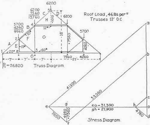
Fig. 283.
Problem 10 Fig. 284 Five Panel Howe Truss, supporting a gravel roof, and plaster ceiling. Ceiling loads added to roof loads. To draw the stress diagram commence with the vertical line oa equals Pl 13,300 lbs. at a scale of 4,000 or 5,000 lbs. to the inch. From a draw a line parallel to AD, and from o a line parallel to DO, the two lines intersecting at d. To complete the stress diagram for joint 2, we have the line da, acting towards a, measure down from a the load of 6,600 lbs. which gives the point b, and from d and b draw lines parallel respectively to ED and BE, intersecting at e. Although the line ed is drawn from d, it acts from e towards d, as the arrow heads must follow each other in succession around the polygon. For joint 3, the stress polygon is od, de, ef and fo. For joint 4, we have fe, starting from the point f, eb, be equals 6,600 lbs., and the line eg which brings us to the starting point f, leaving no room for a line parallel to GF, thus showing that there is no stress in the rod GF, except that due to the ceiling load of 1,600 lbs. It should not be forgotten that to the stress found by scaling the line ed (6,600 lbs.) should be added the ceiling load to obtain the true stress which in this case is 8,200 lbs.
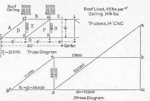
Fig. 284.
To check the stress diagram, by Table XII, the rise of end strut being 9" in 12", the length of do, should be equal to 13,200 x 1-1/3 equals 17,600.
It should be noticed that the stress in the top chord between joints 2 and 4 is just equal to the tension in the tie beam between joints 1 and 3.
Problem II, Figs. 285 and 286. 286 shows the truss and stress diagrams for the six panel Howe Truss shown in Fig. 285. The stress diagram is drawn in the same manner as that in problem 10, only carried one step farther, and presents no difficulties. There is no stress in the center rod except that produced by the ceiling load. Problem 12, Fig. 287. Here we have a very shallow Howe Truss loaded at alternate panel as in Fig. 115. The loads are approximately what they should be for a spacing, c to c of trusses of 14 1/2 ft., with no ceiling loads. The stress diagram for joint 1 is drawn precisely as in all of the foregoing problems. For joint 2 we have the stress FA represented by the line fa and as there is no load at this joint, the next force must be the stress in AG, which will be represented by a horizontal line drawn through a, and the figure must close by a vertical line, representing the stress in GF drawn through f, the intersection of these two lines gives the point g. To complete the stress diagram for joint 3, we already have of, and fg, and draw gh and ho parallel, respectively to GH and HO. For joint 4, we have hg, and ga; measure down from a the load of 8,000 lbs., giving the point b, and from b draw a line parallel to BI, and from h (the point of beginning) a line parallel to IH, the two intersecting at i.
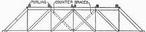
Fig. 285.

Fig. 286.
For joint 5, the stress polygon is oh, hi, ij and jo. For joint 6, the stress polygon is ji, ib, bk and kj. For joint 7, the stress polygon is oj, jk, kl and lo. For joint 8, the stress polygon is Ik, kb, bc and a line from c parallel to CM, which brings us back to the point of beginning, so that cm coincides with ol, and ml is represented by a dot, showing that there is no stress in ML.

Fig. 287.
For the stress polygon for joint 9, we have the line ol, and as lm has no length, and the figure must close by a horizontal line through o, it is evident that there can be no stress in MN, and the stress in NO must equal that in MO.
For resisting the given loads therefore, the rod LM and brace MN could theoretically be omitted, but in practice it is a good idea to put in light members to support the chords and keep them from bending under their own weight. With a ceiling load at joint 11, there would be a stress in these members.
Problem 13, Fig. 288. Howe Truss with but one load at the center. For this method of loading the stress diagram is similar to one-half of the truss diagram, the stress in the rods and braces being uniform while the stress in the chords increases with the number of panels. The maximum bending moment for a beam or truss loaded at the
WL center is ----- , L denoting the span.
In this case = = 32,000. The stress in the tie beams in the center panel of the truss we find from the stress diagram, to be 8,000 lbs. Dividing the bending moment by this stress we have 4 for the quotient, which is the height of the truss - or the maximum stress in the tie beam of a Howe Truss, is equal to the maximum bending moment in foot pounds, divided by the height of the truss in feet and this is true for all Howe Trusses and also for lattice trusses. For example, the maximum bending moment in the truss, Fig. 284 equals 13,200 x 20 - (6600 x 12 + 6600 x 4) equals 158,400 foot-pounds. Dividing by the height we have 26,400 lbs. for the stress in the tie beam at the center.

Fig. 288.
Problem 14, Fig 289. Howe Truss, with inclined top Chord. For this problem we have taken a truss like that shown by Fig. 116. The roof loads were computed at 47 lbs. per square foot and a spacing center to center of trusses of 17 ft. There is no ceiling load. The portions of the top chord beyond joints 2 and 6 (see Fig. 116) receive no strain and are extended merely to facilitate the construction and to stay the truss. The center rod also has no stress, being used merely to prevent the tie beam from sagging. The entire space between the inner brace is therefor designated by a single letter.

Fig. 289.

Fig. 290.
The stress diagram is drawn in exactly the same manner as that in problem II, except that the lines representing the stresses in the top chord are drawn parallel to the slant of the chord instead of horizontal, and as is the case with all nnsymmetrical trusses, it is necessary to complete the diagram for the entire truss. In this problem the stresses are given on the truss diagram, instead of on the stress diagram.
Problem 15, Fig. 290. For this problem we will take the truss shown by Fig. 252, and for which the roof loads were found in example 7, page 235.
The stress diagram for joints I, 2 and 3 are drawn precisely as in problem 8, except that at joint 3 the top chord is inclined. For joint 4 the stress polygon is of, fg, gh, hi, and io. For joint 5, ih, hc, cd, dj, and ji, and for joint 6, oi, ij, jk and ko. It will be seen that inclining the top chord towards the center reduces all of the stresses beyond joint 3.
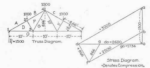
Fig. 291.
Problem 16, Fig 291. Simple Fink truss. The panel loads in this example are for convenience, taken at 1,000 lbs. for any other load the stresses will be increased or decreased in the proportion that the load bears to one thousand. Thus, for panel loads of 3,000 lbs. the stresses will be just three times those given on the stress diagram, provided the panel loads are all equal, which is commonly the case with steel trusses.
The drawing of the stress diagram presents no difficulties. The general shape of the stress diagram will be the same for any inclination of rafter, but the greater the inclination, the less will be the stress in the principal members.
Problem 17, Fig 292. Simple Fan Truss, similar to Fig. 66. The stress polygons should be drawn in the order in which they are numbered. The span and rise of this truss are the same as those of the truss in Fig. 291, and the panel loads correspond to the same weight per square foot of roof. It will be noticed that the principal stresses are a little greater in Fig. 292 than in Fig. 291, because more of the roof load is supported by the truss and less by the wall. The rafter being shorter in Fig. 292, however, the actual amount of steel required will be about the same in the two trusses. Which of the two trusses would be the most economical for any given roof will depend Upon the kind of roof, and how the roofing is supported, as explained on page 58. The truss dimensions in Figs. 291 and 292 are given to show the relative lengths of the members, with a 30 degree pitch.
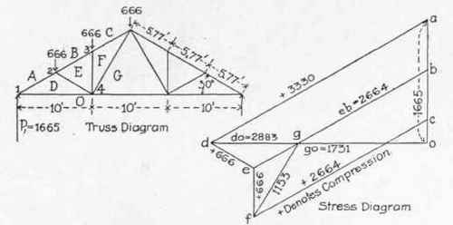
Fig. 292.
They have no bearing on the stress diagram, i. e., with the same panel loads the stresses will be the same for a truss of twice the span, as long as the inclination of the members remain unchanged.
Problem 18, Fig. 293. In this example we have a simple Fink truss with cantilever projections beyond the supports. As usually built, the posts supporting the truss extend to joints 3 and 9, to give lateral stiffness, but for determining the stresses under vertical loads the seats of the truss should be considered to be at joints 2 and 10. In this truss there will be a load at the outer joints equal to one-half of the panel loads, if the distances 1 - 3, 3 - 4 and 4 - 6 are equal.
The stress diagram in this case is commenced by drawing the line ab (Diagram A) to represent the load AB at joint 1, with the arrow heads pointing down, and from a and b, drawing lines parallel respectively to EA and BE. The stress be acts from b towards e, or from the joint, denoting tension, while the stress ea acts towards the joint denoting compression. Next complete the stress polygon for joint 2. We already have the line ae, and the point a, and as the supporting force is OA, its upper end must be at a, and o will be a distance below it equal to 4,500 lbs. We then have for our stress polygon, oa, acting up, ae, ef and fo, the point f being found by drawing a line through o parallel to FO. In this case all of the forces act towards the joint hence all the four members are in compression. Next complete the stress polygon for joint 3. We already have fe and eb, and measure down be equals 1,500 lbs. From c draw a line parallel to CG and from f a line parallel to GF, giving the point g.

Fig. 293.
For joint 4 the stress polygon is gc, cd, dh and hg.
For joint 5 the stress polygon is of, fg, gh, hi and io.
Diagram B shows what the stresses would be if the overhanging projections were omitted. Comparing diagrams A and B we see that the overhanging projections decrease the stress in the rafter above joint 3, by the amount of the stress in BE. The tension in the tie beam between joints 3 and 5, is the same in both cases, but the tension in the center, io, is less in diagram A, also the stress in hi.
For this truss the stresses due to a horizontal wind pressure of 30 lbs. per sq. foot should be computed, and added to those produced by the dead load.
Problem 19, Fig. 294. Eight panel Fink Truss with rafter divided into equal panel lengths.
No difficulty should be experienced with the stress diagram until we come to joint 4, where there are three unknown forces. There are two or three ways of getting over this difficulty, the simplest one, in the opinion of the author, being to assume, for the moment that a strut extending from joint 5 to joint 6 is substituted for members HI and IK, which would leave but two unknown forces at joint 4. Proceeding then, with the stress polygon for joint 4, we have already drawn the lines gf and fb, and we measure down from b, a distance of 1,000 lbs., which gives the point c. Then from c and g draw lines parallel respectively to CI and HG, intersecting at i'. Next, complete the stress polygon for joint 5 on the assumption that the strut IK is placed, as shown by dotted line, instead of by the full line. We have for the stress polygon for this joint the line i'c and proceed to measure down from c the load of 1,000 lbs. giving the point d. From d and V draw lines parallel respectively to DK, and to the dotted line, intersecting at k. We now proceed to complete the stress diagram for joint 6, with the strut as shown by dotted line.
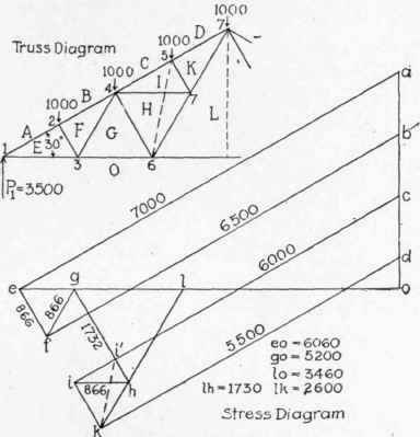
Fig. 294.
We have already drawn the lines og, gi', i'k, and from k draw a line parallel to KL intersecting og at 1. Now the stresses in KL and LO are not affected by changing the position of the strut, so that the points k and 1 are in their correct position. Returning to the stress polygon for joint 6, and proceeding as though the dotted line had not been drawn, we have the correct lengths for og and lo, and if we prolong gi' until it intersects Ik at h, the lines gh and hi will correct-lv represent the stresses in GH and HL. Returning to joint 4 and considering that the tie IH is now in place, we have hg, gf, fb, bc and from h draw a line parallel to IH, until it intersects ci', prolonged, giving the true position of the point i. For joint 5, we now have ic, cd, dk, and a line from i parallel to KI which should pass through the point k, which completes the stress diagram for one-half of the truss.
As a matter of fact, when the panel loads and divisions of the rafter are all equal, as in this example, the line ik will lie in the continuation of ef, so that the points i and k can be found directly by continuing the line ef, but if the panel loads or divisions of the rafter are not equal, or there are loads at joints 3 and 6, then the points i and k will not be in the continuation of ef and it will be necessary to find them by the process described above, which applies to any manner of loading, or any inclination of the rafter.
The stresses given on the stress diagram are given closer than they can be scaled, in order to show the exact stresses for panel loads of 1,000 lbs., and an inclination of 30 degrees. For any 8 panel Fink truss, evenly divided, and with this inclination, the stresses will be increased or diminished from those shown in direct proportion to the panel loads. Thus for a truss of 70 ft. span, and panel loads of 4,800 lbs., the stresses will be 4.8 times those given in Fig. 294. It is interesting to note that the stresses EF, FG, HI and IK are all equal, and that the stress in HG, is just twice that in EF or IK.
Problem 20, Fig. 295. Eight panel Fink Truss with loads at the lower joints.
As a rule, those buildings in which Fink trusses are used have no ceiling, but the trusses are often required to support shafting, tracks or pulleys, for hoisting machinery, etc., and sometimes a gallery except for the change due to the ceiling loads the stress diagram is drawn exactly as in Fig. 294. The line oa represents one-half of the total load on the truss. For the stress polygon for joint 3 we start by measuring up from o, a distance equal to the load at the joint which gives the point r. We then have ro, oe, ef and from r and f draw lines parallel, respectively to GR and FG, intersecting at g. For joints 4, 5 and 6 the stress diagram is first drawn on the assumption that the dotted line is substituted for HI and IK, as explained in Problem 19. For the stress polygon at joint 6 we start by measuring up from r the load of 500 lbs. giving the point s. We then have sr, rg, gi' and i'k, and from k draw a line parallel to KL until it meets a horizontal line drawn through s, at 1. Then working backwards, we have for joint 6, 1s, sr, rg, and gh and hi must close the figure. Knowing gh we can readily obtain ih and ik.

Fig. 295.
Problem 21, Fig. 296. Eight Panel French Truss, like Fig. 69, except that the tie from joint 1 to joint 6 is inclined, the stress diagram is drawn precisely as explained in Prob. 19.
It should be noticed that inclining the tie, materially increases the stresses in all members except the struts.
Problem 22, Fig 297. Fink Truss with vertical struts. The stress diagram is drawn in the same manner as described in Prob. 19, first finding the point k by means of the dotted line, and working backwards from 1 and g to find the point h. It is interesting to note that with vertical struts the stress is uniform throughout the rafter, and that the stress in all of the web members is increased. As the vertical struts are shorter than the inclined struts, the actual amount of steel required for the truss in Fig. 297 will be about the same as for the truss in Fig 294, when the span is not over 70 ft. and with a rise of 30 degrees or more.
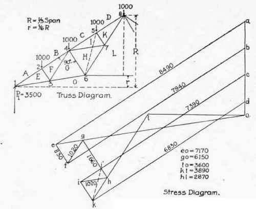
Fig. 296.
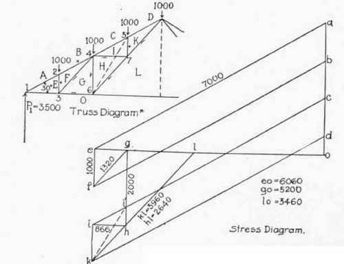
Fig. 297.
Problem 23, Fig. 298. Twelve-panel Truss (similar to Fig. 73). The stress diagram presents no difficulties until we come to joint 8, when it is necessary to assume that the members ST and TU are supplanted by a strut from joint 9 to 10, as in the last three problems. Omitting the members TS, TU, the stress polygon for joint 8 is rn, nd, de, et' and t'r. For joint 10 the stress polygon is t'e, ef, fu and ut' for joint 9, it is or, rt', t'u, ux and xo. This gives the point x, which will enable us to obtain the point s, by continuing rt' until it meets ux and s. The true stress polygon for joint 8 will now be sr, rn, nd, de, et and ts, and for joint 10, te, ef, fu and ut.

Fig. 298.
Problem 24, Fig. 299. Truss like Fig. 75.* The stress diagram is readily drawn until we come to joint 6, when it is necessary to find t' u, and v, as in Prob. 23. At joint 9 we also have three unknown forces, viz., FA', A'X and XV. To find the point a' it is necessary to first find the stress in XA'. This can be done by drawing a stress diagram for the portion of the truss included within the lines 9-15, 15-14 and 14-9, considered as an independent truss. The stress diagram for this portion of the truss is shown by diagram B, which gives the correct stress for all of the web members. Now, for the stress diagram for joint 9, we have vu, ue and ef. Draw a line from f parallel to FA' and a line from v parallel to VX. The stress line for A'X must connect these two lines and must be equal in length to the line a'x, Diagram B, and aso parallel to A'X. By means of a parallel ruler or two triangles draw a line parallel to A'X, intersecting the lines drawn through f and v, and move the ruler up or down, until the length of a'x is just equal to the length given by diagram B. This can readily be done by means of dividers. We thus obtain the points a' and x in the full stress diagram after which it is easy to draw the stress polygons for all remaining joints. When the truss rafter is divided into equal lengths, and the load is uniform, as in this example, the point a' will be in line with u and v, but if the rafter is not divided evenly, then the point a' will not be in a line with u and v, but the process for finding the point a' applies to any condition of loading or division of the rafter. Problem 25, Fig. 300. Warren Triangular Truss. By drawing the stress polygons in the order in which the joints are numbered, no joint has more than two unknown forces, so that there should be no difficulty with the stress diagram.
*The stresses in the monitor should, theoretically, be determined before attempting the truss diagram. For they will not have just the same effect at the truss joints, to which the monitor is attached, as would a uniformly distributed roof load. Practically the loads at the truss joints mentioned may be considered to be those due to panel loads the same as at the other joints.
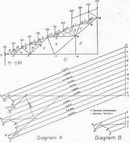
Fig. 299.
Stresses not given on the engraving.
lo, 2625, no, 2500, vo, 2125, zo, 1375 xz, 740, zf 1335; zi 1475. vs. 375; vu, 500, Mn = st = 125.
b'c = f'h = 147. lm, = tu = a'b = d'e = h'i' = 928.
nr = rs = 155. c'd = e'f = 195.
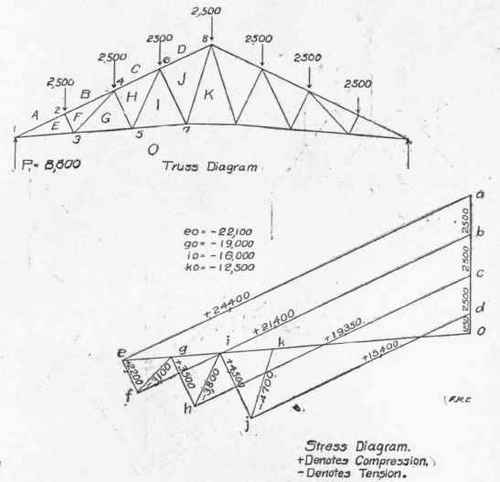
Fig. 300.
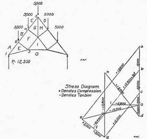
Fig. 301.
Problem 26, Fig. 301. Truss like Fig. 77. The stress diagram for this truss is drawn in the same manner as described in the preceding problems, going from joint to joint in the order in which they are numbered.
Problem 2/, Fig. 302. Truss like Fig. 80. In starting the stress diagram for this truss the force next in order to the supporting force going around like the hands of a clock is the stress in AF, which, being horizontal, gives a different stress diagram from that of any of the trusses thus far considered. It should be remembered, however, that the process of drawing the stress diagram is the same, whatever the inclination of the members, and it is only in cases where there are three unknown forces that any difficulty arises.

Fig. 302.
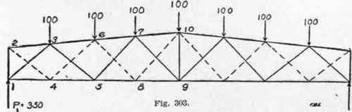
Proceeding with the stress diagram for this truss in the order in which the joints are numbered, no joint has more than two unknown forces. Problem 28, Figs. 303 and 304. Lattice Truss. Fig. 303 shows the truss diagram for a steel lattice truss of similar design to that shown in Fig. 82, except that in Fig 303 we have introduced a vertical member at the center. This truss is really a combination of two trusses, one laid over the other, as it were, with the chords coinciding. Trust diagrams "A" and "B" in Fig. 304 show the two trusses of which Fig. 303 is composed, diagram "A" representing the portion of Fig. 303 shown by full lines, and a diagram "B" the truss whose web members are shown by dotted lines. By referring to Fig. 303 it will be seen that the loads at joints 3 and 7 must be supported entirely by the truss shown by diagram "A", and the load at joint 6 must be supported by the truss shown by diagram "B". Joint 10, on account of the center vertical member, is common to both trusses, and we should, therefore, assume that 50 lbs., is carried by one truss, and 50 lbs. by the other. The joint loads on
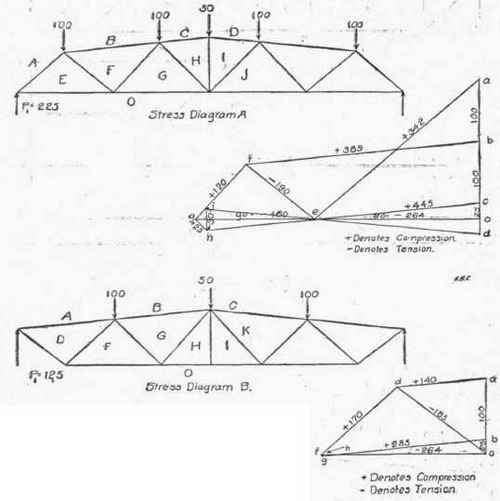
Fig. 304.
Fig. 303 are therefore divided, as shown by diagrams "A" and "B", Fig. 304. Drawing the stress diagrams in the manner described for all of the preceding problems we obtain the stresses indicated on the diagrams.
To obtain the real stress in the chords it will be necessary to combine the stresses given by the two stress diagrams. Thus, the stress in the top chord between joints 2 and 3 (Fig. 303) is 140 lbs. from diagram "B" and o, from diagram "A". Between joints 3 and 6 the stress is 385 lbs. from diagram "A" and 140 lbs. from diagram "B". Between joints 6 and 7 the stress is 385 + 285 lbs. and between joints 7 and 10 the stress is 507 + 285 lbs.
In the same way, the stresses for the bottom chord are 264 lbs. between joints 1 and 4, 528 lbs. between joints 4 and 5, 770 lbs. between joints 5 and 8, and 797 lbs. between joints 8 and 9.
It should be-noted in connection with stress diagrams B, that there is no stress in the vertical center member, from the center load on this truss, and even in the truss shown by diagram "A" the stress on the center member is but 30 lbs. By considering that-the entire load at joint 10 is supported by truss "B" the diagonal GH, Diagram A is put in compression, causing a tensile stress in HI, with the inclination of. top chord shown by the diagrams.
The load at joint 10 could be divided between the two trusses in such a ratio, however, so that there would be no stress at all in GH and HI, jand ...hence the center member can be omitted, and probably would be in light trusses. The ratio in which the centre load should be divided between the two trusses to give no stress in GH and HI will depend upon the inclination of the top chord, and when the inclination reaches a certain angle, a vertical tie in the centre becomes absolutely necessary to hold down the apex.
With a horizontal top chord there is no necessity or advantage in a vertical center member.
None of the diagonal members of the truss shown by Fig. 303, enters into both of the component trusses, hence each has only the stress shown by the stress diagram for the truss to which it belongs. Thus, the stress in diagonal 1-3, is 342 lbs., and in 2-4, 185 lb., the former being in compression and the latter in tension.
Problem 29, Fig. 305. Suspended Pratt Truss. The stress diagram presents no difficulties when drawn in the order in which the joints are numbered. The diagram, like many others, is given merely to show the reader its appearance when correctly drawn, and to serve as a check when drawing the stress diagram, for any particular truss.
When this truss sustains unsymmetrical loads the stress in the diagonals nearest the center may change to compression instead of tension.
Problem 30, Fig. 306. Simple Scissors Truss. For this problem we have taken the center lines of the truss shown in Fig. 155, which supports a shingle roof and plastered ceiling. The actual weight of the materials in the roof and truss, exclusive of lath and plaster, is in the neighborhood of 13 lbs. per sq. ft. of roof surface. The loads given on the truss diagram were computed on the basis of 43 lbs. per sq. ft. of roof surface, and 12 lbs. per sq. ft. additional for plastered ceiling. It should be noted that half of the weight of the horizontal ceiling is supported at the apex joint. To draw the stress diagram, commence by drawing a vertical line oa = 7,140 lbs. (one-half of the load on the truss) and from a draw a line parallel to the rafter and from o, a line parallel to the tie beam. Where these two lines intersect place the letter d. Then ad represents the stress in AD and do the stress in DO. For the stress polygon at joint 2, we have da, and from a measure downwards the load of 4,730 lbs. giving the point b. From the point of beginning d, draw a line parallel to ED, and from b, a line parallel to the rafter BE, and at the point of intersection of these lines place the letter e. It should be noted that ed acts towards the joint denoting compression, while DO is in tension. For the stress polygon for joint 3, we have eb, measure downward, be = 4,820 lbs., and from e and c draw lines parallel respectively to FE and CF, intersecting at f. We now have the stress lines for all of the members of the truss, as the stresses are the same in each half, and scaling the lines of the stress diagram we obtain the stresses indicated on the engraving.

Fig. 305.

Fig. 306.
Continue to:
My Books

