Flat Roof Construction
Description
This section is from the book "Building Construction And Superintendence", by F. E. Kidder. Also available from Amazon: Building Construction And Superintendence.
Flat Roof Construction
47. By the term "flat roof" is here meant a roof in which the rise is not greater than 1 1/2 or 2 inches to the foot, the exact pitch being determined by the kind of roofing to be used.
Pitch of Flat Roofs. - For pitch and gravel (composition) roofs the rise should not be less than § inch nor greater than § inch to the foot; for tin or copper, standing seam steel roofing and canvas roofing a pitch of 1/2 inch to the foot is sufficient, but there is no objection to a steeper pitch, unless it be that the steeper pitch requires the greater amount of material, and hence weighs and costs more.
Layout. - As a rule,where flat roofs are supported by trusses, the trusses are placed across the building in parallel lines, with their ends resting on or built into the side walls. In supporting the roof from the trusses either of two methods may be adopted. The more common method, probably, is to rest the ends of the rafters directly on the top chords of the trusses, as shown in Fig. 113, the trusses being made of different heights, so as to give the desired pitch to the rafters. This method answers very well for wooden roofs of moderate span, but when the span is 60 feet or over it will be more economical to support the rafters on purlins, as shown in Fig. 114. The advantages of the latter method are, that the purlins being placed over the joints of the trusses, no transverse strain is produced in the top chord, and the roof is better tied to the walls in both directions. The use of purlins also permits of smaller sizes for the rafters and the placing of the trusses further apart. By bracing the purlins as shown at A, Fig. 114, the trusses may be spaced from 20 to 24 feet apart. The purlins should be spaced from 8 to 12 feet apart, according to the width of the panels of the trusses.
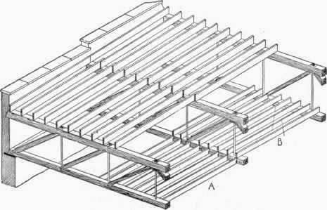
Fig. 113.

Fig. 114.
If it is necessary to use shallow trusses, the purlins may be placed over every other joint as in Fig. 115.
The forms of construction above described are also applicable to deck roofs, and the same principles apply to them as to flat roofs.
The ceiling joists will naturally extend from truss to truss, either resting on top of the tie-beams, as shown at B, Fig. 113, or framed between them, as at A. If framed between the tie beams the bottom of the joists should be kept 1/2 inch below the bottom of the beams, to allow for furring the latter, if the laths are to be applied directly to the joists. If the ceiling is to be "strapped" or "cross furred" the joists may be flush with the tie-beams. If the spacing of the trusses exceeds 16 feet it will be more economical to support the ceiling joists on the tie-beam of the trussed purlins.

Fig. 115. - Ten-Panel Howe Truss.
Types of Trusses for Flat Roofs. - If wooden trusses are to be used the Howe Truss will generally prove the most economical for spans up to 90 feet. For longer spans it may be cheaper to use a segmental arch truss, as shown in Figs. 58 and 59 of Chapter 1.
If the roof is built in a timber country, the lattice truss, as described in Section 12, may be employed.
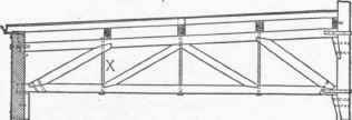
Fig. 116.
The rules which should govern the height and proportions of Howe and Lattice trusses are given in Sections 10 and 12, and Tables I and II will be found useful in making the preliminary drawings.
If the pitch of the roof is parallel with the trusses, as is frequently the case in buildings having a clerestory above the central portion, the top chord may be given the same inclination as the roof, as shown in Fig. 116, the minimum ratio of height to span being taken on the line of the rod X.
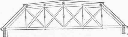
Fig. 117.
For deck roofs the trusses may be made of the shape shown by Fig. 117, and for such roofs, it will be well to put in counter-braces, to resist the wind pressure against the sides of the roof.
48. If steel trusses are to be used, one of the types shown by Figs. 80 to 85, Chapter II (Foundations On Compressible Soils), will generally be most economical, the particular type to be selected depending largely upon the span, Figs. 80 and 81 being best adapted to spans under 50 feet and Figs. 82-85 to spans over 50 feet. For spans exceeding 100 feet, a truss such as is shown in Fig. 88 will generally be as economical as any, when the truss is supported by brick walls.
With steel trusses it will nearly always be more economical to use purlins, supported at the joints of the trusses, for carrying the jack rafters or sheathing. Where an absolutely fireproof roof is not required, an economical construction, for spans up to 60 feet will be to have heavy timber purlins, from 6 to 8 feet center to center, and on top of these place plank sheathim; to receive the roofing. Such construction would resist fire fully as long as an unprotected steel truss.
For strictly fireproof construction, I-beam purlins or rafters will generally be required, spaced from 5 to 8 feet on centers, with tile or concrete filling between. For spans up to 50 feet, it will generally be cheaper to support the roof beams on the truss, the joints in the latter being spaced to suit the beams. For greater spans, it will be more economical to space the trusses twenty feet or more apart, and to support the roof beams on heavy I-beam or trussed purlins.
49. Spacing Of Wooden Trusses
For spans up to 75 feet, the most economical spacing will be from 12 to 16 feet. For greater spans, the spacing should be from 16 to 24 feet.
Spacing of Steel Trusses. - With steel trusses, the greatest economy of material is obtained, when the distance center to center of trusses is about one-fifth of the span, but as the cost of manufacture varies almost directly as the number of trusses, a spacing of from one-fourth to one-third of the span will generally be most economical, all things considered. Table IV. and the examples given in Chapter VI (Coliseums, Armories, Train Sheds, Exposition Buildings, Etc). will give a good idea of the usual spacing for different spans and types of steel trusses.
Continue to:
My Books

