Floor Constructions. Part 7
Description
This section is from the book "Building Construction And Superintendence", by F. E. Kidder. Also available from Amazon: Building Construction And Superintendence.
Floor Constructions. Part 7
304. "Guastavino" Arch (Patented, and erected only by R. Guastavino)
This is the other type of segmental tile arch referred to in the previous section. It is not a true segmental arch, but is constructed on the dome principle.
Arch or dome shells are built of small rectangular tiles of hard terra cotta about 6x8 inches and ¾ inch thick, cemented together in three or more thicknesses, depending upon the size of the vault. The tiles are laid on arched centres one course at a time, and each course breaks joint with that below. The first layer is usually laid in plaster of Paris and the others in Portland cement. The thickness of the shell is generally increased at the haunches or reinforced by a light arch sprung against the top of the girder web. Each dome generally covers the space between four columns, girders being run from column to column both ways of the building and tied together at their ends. Entire rooms, when surrounded by brick walls and not more than 20x40 feet, may also be covered by a single vault. The strength of these vaults, considering their thickness, is very-remarkable.
* Engineering Record, April 14, 1894.
This system does not appear to be applicable to stores and office buildings on account of the shape of the ceiling, but for public buildings and buildings having solid masonry walls or piers, and where a curved soffit is in keeping or desirable, it possesses great advantages. It has been used in a number of buildings in New York and Boston, and in a few instances in other cities. It was used throughout the Boston Public Library.
305. The Fawcett Ventilated Fireproof Floor
This floor is constructed of dense tile and cement concrete, and differs entirely from those previously described.
The tiles are tubular in form, and, instead of being made to form an arch, are used as lintels, as shown in Fig. 186. They are made of fire or chimney pot clay in pieces about 2 feet long. The floor beams for this system of construction are spaced 2 feet apart from centres, and the lintels are fixed between them with their diagonals at right angles with the beams.
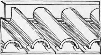
Fig. 186.
The end of each bay is squared by cutting (during manufacture) an ordinary lintel parallel to the diagonal; the piece cut off, when reversed, goes on the other end. Thus the ends and sides of all lintels are open next the walls. These are called "splits."
The lintels being in position, specially prepared cement concrete is filled in between and over them, which takes a direct bearing upon the bottom flange of the beams, thus relieving the lintels of the floor load, which is taken by the iron and concrete, the lintels forming a permanent fireproof centring, reducing the dead weight of the floor about 25 per cent, and saving about half the concrete.
The lintels bear on the beams in such a way as to entirely encase the bottom flange without being in contact with it, a clear ½-inch space being left for the passage of air.
The peculiar feature of this system is the circulation of air provided through the tubular lintels and under the flanges of the beams. Cold air is admitted (through air bricks in the external walls) into a portion of the open ends or sides of the lintels, and passes through them from bay to bay under the beams, both transversely and longitudinally of the floor, as shown in Fig. 187.
It is claimed that the chief fire-resisting agent in this floor is not so much the terra cotta or the concrete as the cold air, and that the circulation of air through the floor and around the beams will actually prevent the iron from ever getting hot.
The Fawcett Company claim that their floors have never been injured by fire and water beyond what could be repaired by replastering the ceiling and redecorating the walls.

Fig. 187.
The steel floor beams, being spaced so near together, can be made very light (5-inch beams being generally used for office floors, schools, etc., up to 16 feet span), and as the total thickness of the floor from under side of plaster to top of flooring is but 5 inches greater than the depth of the beams, the floors are consequently much thinner than in almost all other systems.
The floor is finished on top by bedding 2X3-inch nailing strips in the concrete above the steel joist, as shown in Fig. 187, and nailing the flooring to these strips in the usual way.
Repeated tests have proven that the strength of the tile and concrete filling is fully equal to that of the beams, so that the carrying capacity of the floor is only limited by that of the beams. For beam spans not exceding 18 feet, the cost of the structural steel work in place does not exceed that of the structural work for the flat arches previously described.
The advantages claimed for this system, aside from its fireproof qualities, are : Saving in height of story from 6 to 8 inches; saving in freight, hauling and hoisting, of about 50 per cent.
No tie-rods are required, and a more even distribution of the floor weight on the walls is secured. No centres are required for setting, and ordinary unskilled labor can be employed for all portions of the work.
The weight of the floor is much lighter than that of any other system using tile filling between the beams, with the possible exception of the Guastavino floor.
This floor has been placed in a great many fine buildings in England, and lately in many buildings in Philadelphia and other Eastern cities. It certainly has many good points and deserves investigation.
Continue to:
My Books

