Examples For Practice Roof Coverings #2. Part 8
Description
This section is from the book "Cyclopedia Of Architecture, Carpentry, And Building", by James C. et al. Also available from Amazon: Cyclopedia Of Architecture, Carpentry And Building.
Examples For Practice Roof Coverings #2. Part 8

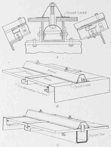
Fig. 73. "Paradigm" Method of Glazing.
An extended set of specifications is not required for the design of ordinary roof trusses. In addition to the information regarding the weight of trusses, the weight of roof covering, the snow load, and the wind load, the use of Table VIII will be found to be all that is necessary in order to design cross-sections of the various members, once the stresses are determined.
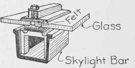
Fig. 74. " Anti-Pluvius " Method of Glazing.
Table VIII
Allowable Unit=Stresses, Medium Steel | ||||||||||
For Shear | 10 000 | per | square | inch. | ||||||
For Bearing | 20 000 | " | " | " | " | |||||
For Tension | 15 000 | " | " | " | " | |||||
For Bearing of Steel on Masonry.. | 250 | to | 400 | " | " | " | " | |||
For Compression.. | P | = | 24 000 | - | 110 | l / r | ||||
In case the stresses are those due to crane loads, the unit-stresses in tension and compression indicated in Table VIII should be reduced 1/3 and 1/2 respectively.
Members of the lateral bracing and their connections may be allowed an increase of 25 per cent over the unit-stresses there indicated.
In the equation above given "For Compression," l is the length of the member in inches, and r the least radius of gyration. The ratio of l/r should never be greater than 120.
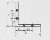
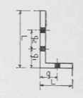
The gauge line or gauge is the line on the flange of a shape, on which the rivets are placed. In angles and channels it is located by giving its distance from the back of the shape; in the case of I-beams the distance between two gauge lines on opposite sides of the web is indicated. Some angles have double gauge lines, in which case the rivets are placed first on one and then on the other; this is called staggering. Fig. 75 shows gauge lines for various shapes.

Fig. 75. Gauges for Angles, Channels, and I-Beams.
Rivets 3/4 inch in diameter are generally used in legs of angles 3 to 4 inches long or greater. For the gauge lines and the maximum sizes of rivets to be used in angles, see Table IX. For similar data for channels and I-beams, see Carnegie Handbook, pp. 177-185.
It is often desirable to express the length in feet instead of inches, in which case the formula becomes:
P = 24 000 - 1 320 L/r
Table IX. Gauges And Maximum Allowable Rivets For Angles

L | g | Maximum Rivet or Bolt | L | g | Maximum Rivet or Bolt | L | g | Maximum Rivet or Bolt | |
8 | 4½ | 7/8 | 3½ | 2 | ⅛ | 2 | 1 1/8 | ½ | |
7 | -4 | 7/8 | 3 | 1¾ | 7/8 | 1¾ | 1 | ½ | |
6 | 3½ | 7/8 | 2¾| | 1 5/8 | ¾ | 1½ | 7/8 | 3 ■ | |
5 | 3 | 7/8 | 2½ | 5/8 | 1¼ | ¾ | 3 8 | ||
4 | 2¼ | 7/8 | 2¼ | 1¼ | i | l | 9/16 | ¼ | |
L | g1 | g2 | L | g1 | g2 | ||||
8 | 3 | 3 | 6* | 2½ | 2¼ | ||||
7 | 2½ | 3 | 5 | 2 | 1¾ | ||||
6 | 2¼ | 2½ |
* When thickness is ¾ inch or over.
For convenience in designing, the values of L ÷ r should be plotted as ordinates, and the resulting values of P as abscissa?, on cross-section paper, and the curve drawn in. Then the value of P for any given value of L ÷ r may be taken at once from the diagram without the labor of substituting in the above formula.
The bearing value of a rivet in a plate of given thickness is equal to the thickness of the plate, times the diameter of the rivet, times the allowable unit bearing stress. The value of a rivet in single shear is equal to the area of the cross-section of the rivet, times the allowable unit shearing stress. The bearing values of rivets of different diameter in plates of different thickness, and the shearing values of rivets of different diameter, are given in Table X, the unit-stresses being as given above.
Table X. Bearing And Shearing Values Of Rivets
Diameter of Rivet (Inches) | Single Shear (at 10 000 lbs. per sq. in ) | Bearing in Different Thicknesses of Plates (at 20 000 lbs. per sq. in.) | |||||||
¼ in. | 5/16 in. | f in. | 7/16 in. | ½ in. | 9/16 in. | ⅝ in. | 11/16 in | ||
½ | 1 960 | 2 500 | 3130 | 3 750 | |||||
9/16 | 2 480 | 2 810 | 3 520 | 4 210 | 4 920 | ||||
⅝ | 3 070 | 3130 | 3910 | 4 690 | 5 470 | ||||
11/16 | 3 710 | 3440 | 4 290 | 5160 | 6010 | 6 880 | |||
¾ | 4 420 | 3 750 | 4690 | 5 630 | 6 560 | 7 500 | 8 440 | ||
13/16 | 5 180 | 4 070 | 5 080 | 6 090 | 7110 | 8120 | 9150 | 10 160 | |
⅞ | 6 010 | 4 380 | 5 470 | 6 570 | 7 660 | 8 750 | 9 840 | 10 940 | 12 040 |
Continue to:
My Books

